
Forehead support for facial mask

Inactive Publication Date: 2006-01-19
RESMED LTD
View PDF99 Cites 19 Cited by
  • Summary
  • Abstract
  • Description
  • Claims
  • Application Information

AI Technical Summary

Benefits of technology

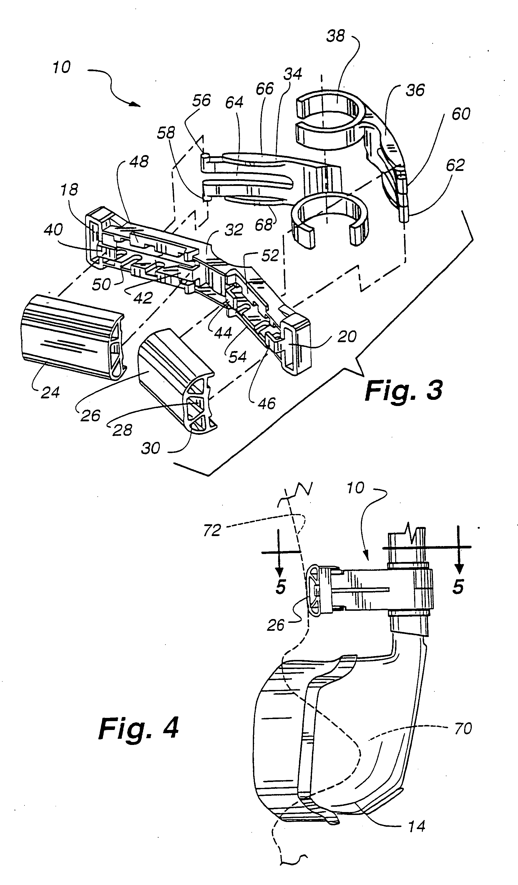
[0010] The present invention is directed to an improved forehead support for nasal and facial masks. In particular, the present invention utilizes a dual cantilevered forehead-support which preferably utilizes dual contacts which are arranged at an obtuse angle with respect to one another and which may be easily adjusted for different forehead protuberances. Preferably, the forehead support has two arms extending from the mask or gas supply line, with the two arms engagable into a bridge system wherein the arms may be adjusted to different positions on the bridge allowing optimal positioning of the mask on the face. This achieves even pressure of the mask on the face. The mask also provides an excellent fit which limits movement of the mask during sleep. The forehead support is adjustable such that the support is closer or further away from the front plane of the facial mask. The bridge supports the pad or pads which contact the wearer's forehead. The support also may allow the mask to be secured such that more pressure is applied to one area of the mask, to seal a leak for example.
[0011] The present invention allows the mask user to adjust the angle of the mask to the face. This is possible due to the two point contact of the forehead support to the forehead working in combination with the point of contact of the mask to the face. The system thus has three points of contact, wherein the forehead pads provide two contact points and the mask to the face is a third point of contact. Adjusting the angle of the forehead pads or the distance of the legs to the forehead pads adjusts the angle of the mask vis-a-vis the face of the user. This unique system provides a mask system which can be adjusted to fit the different face angles or profiles required by users.

Problems solved by technology

One of the problems that arises with the use of the mask is that in order for the straps to be tight, the mask is compressed against the wearer's face and may push unduly hard on the wearer's nose.
This is oftentimes uncomfortable for the patient, and the adjustability of the distance of the pad for different forehead protuberances oftentimes was difficult if not impossible to be performed.
Finally, a single contact point may apply too much pressure at the single point.

Method used


Image

  • Forehead support for facial mask
  • Forehead support for facial mask
  • Forehead support for facial mask

Examples


Embodiment Construction

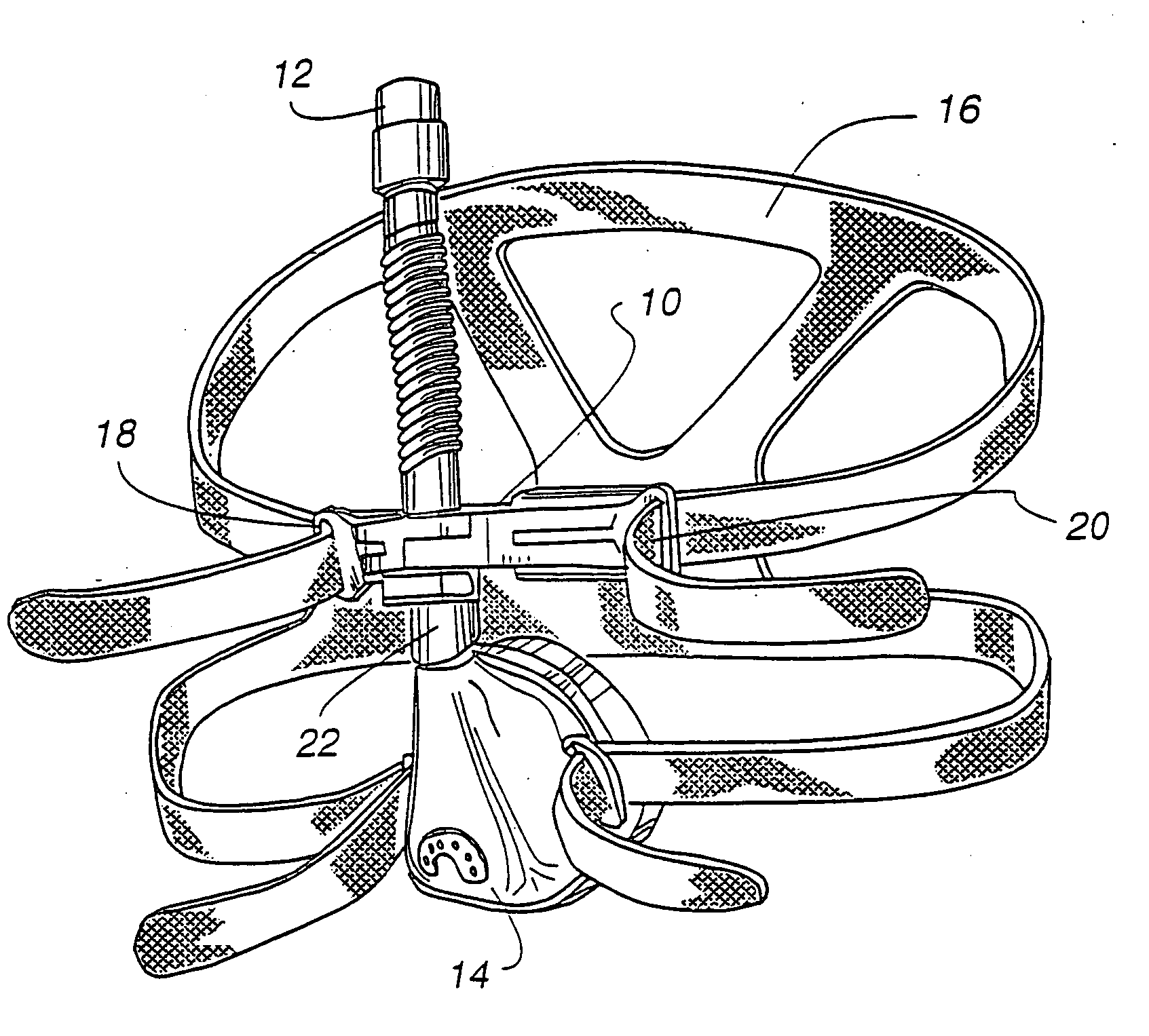
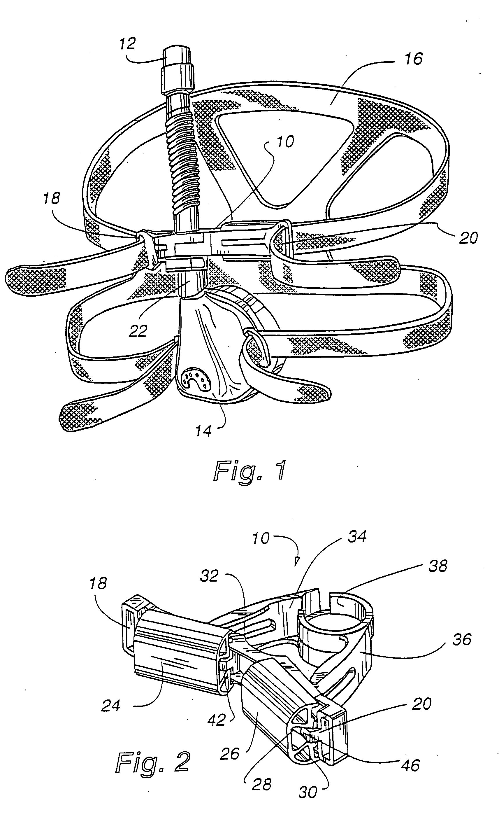
[0022]FIG. 1 shows a general perspective view of the forehead support 10 of the present invention. The forehead rest or support 10 is attached to an extending airflow tube 12 from the mask 14. The mask 14 and forehead support 10 are shown with headgear 16 which secures the mask 14 to the head of a patient. The headgear 16 may take a variety of forms, with one example being shown as 16. As can be seen in FIG. 1, preferably the headgear 16 loops through the forehead support 10 at 18 and 20. This pulls the forehead support 10 against the forehead, thus creating a snugly fitted mask 14 and also provides a stabilizing member for the mask 14.

[0023] The mask 14, shown in FIG. 1 is merely one example of a mask which can be used with a forehead support, but any respiratory mask could be used. A full face mask which may cover the entire face or just both the nose and mouth could be used, for example. Additionally, the airflow tube 12 could be extending from the bottom of the mask 14, thus th...


PUM


Abstract

An adjustable forehead support for a nasal mask. The present invention discloses an adjustable forehead support for a nasal or full-face mask wherein the forehead support may be adjusted for the different shapes and sizes of a facial profile. The forehead support utilizes a dual-arm system which adjusts the position of the forehead support vis-à-vis the mask and / or air flow tube. The angle of the mask to the face may be adjusted with the present invention.

Description

FIELD OF THE INVENTION [0001] The present invention Generally relates to an improved comfort device to be used with a nasal mask. In particular, the device is useful in combination with masks which are used for the treatment of respiratory conditions and assisted respiration. The invention assists in fitting the mask to the face as well. BACKGROUND OF THE INVENTION [0002] Nasal masks are commonly used in the treatment of respiratory conditions and sleep disorders by delivering a flow of breathable gas to a patient to either assist the patient in respiration or to provide a therapeutic form of gas to the patient to prevent sleep disorders such as obstructive sleep apnea. These nasal masks typically receive a gas through a supply line which delivers gas into a chamber formed by walls of the mask. The mask is generally a semi-rigid mask which has a face portion which encompasses at least the wearer's nostrils. Additionally, the mask may be a full face mask. The mask is normally secured...

Claims


Application Information

Patent Timeline
IPC IPC(8): A62B18/02A62B18/08A61M16/06
CPCA61M16/06A61M16/0683A61M16/0638A61M16/0633A61M2210/0618A61M16/065A61M16/0655A61M16/0644
Inventor KWOK, PHILIP RODNEYGRANT, WILLIAM EDWIN JOHNMATCHETT, ROBERT STEPHEN
Owner RESMED LTD
Learn More