Optical disc, optical disc recording device, optical disc recording method

a technology of optical discs and optical discs, applied in the field of optical discs, optical disc recording devices, optical disc recording methods, can solve the problems of more and the optical disc drive spends more time waiting for recording or playback, so as to achieve the effect of reducing the time required for the learning process to determine the recording/playback conditions

Inactive Publication Date: 2006-01-19
PANASONIC CORP
View PDF10 Cites 20 Cited by
  • Summary
  • Abstract
  • Description
  • Claims
  • Application Information

AI Technical Summary

Benefits of technology

[0005] The present invention is directed to resolving the foregoing problems, and an object of this invention is to provide ...

Problems solved by technology

However, determining the recording/playback conditions more precisely by means of this learning process means that the le...

Method used


Image

  • Optical disc, optical disc recording device, optical disc recording method
  • Optical disc, optical disc recording device, optical disc recording method
  • Optical disc, optical disc recording device, optical disc recording method

Examples


embodiment 1

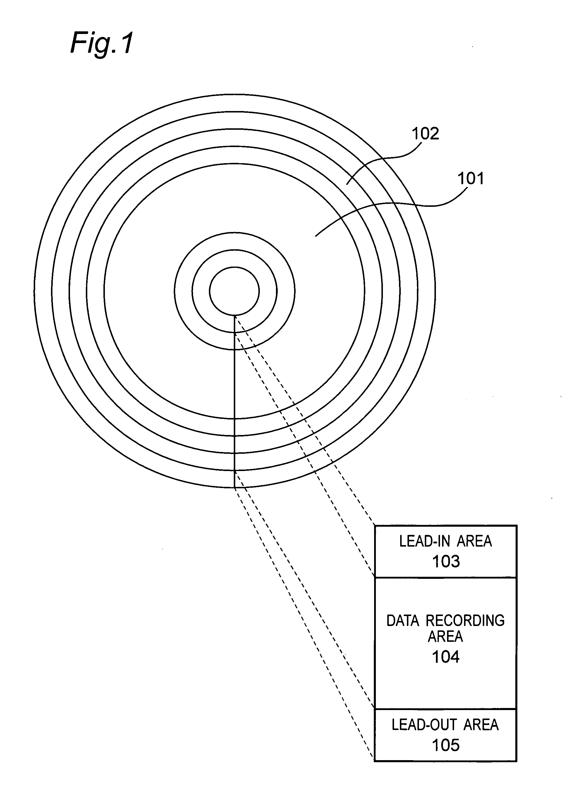
[0036]FIG. 1 shows the arrangement of a data recording medium 101 according to a first embodiment of the present invention.

[0037] This data recording medium 101 is an optical disc having a plurality of concentric tracks 102. Alternatively, a single spiral track 102 or a plurality of spiral tracks 102 could be formed to the optical disc 101.

[0038] The track area of the optical disc 101 includes a lead-in area 103, data recording area 104, and lead-out area 105.

[0039] Parameters required to access the optical disc 101 are recorded in the lead-in area 103. The lead-in area 103 is formed at the inside circumference portion of the optical disc 101.

[0040] The lead-out area 105 could also be used to record parameters required to access the optical disc 101. The lead-out area 105 is located at the outside circumference portion of the optical disc 101.

[0041] Data is recorded and reproduced in the data recording area 104.

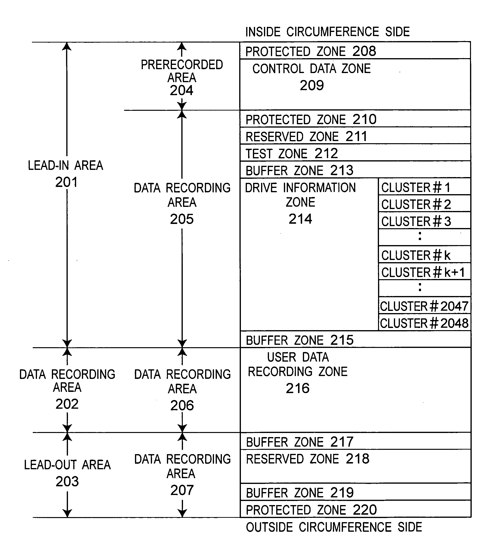
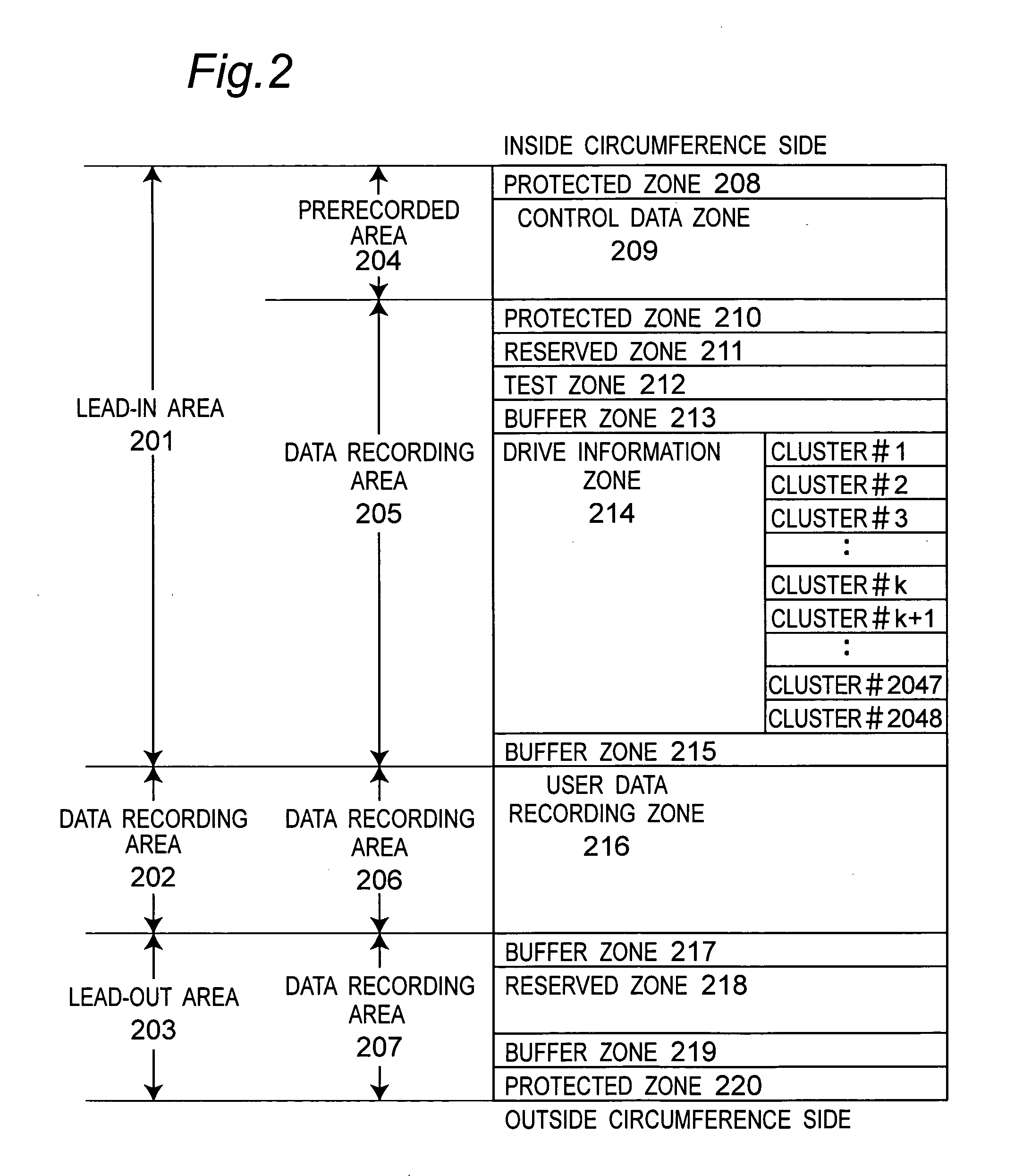
[0042]FIG. 2 shows the logic structure of the lead-in area 103, da...

embodiment 2

[0095]FIG. 13 shows the structure of a single-side, two-layer optical disc according to a second embodiment of the present invention.

[0096] As shown in FIG. 13 this optical disc has a first substrate 601, first recording layer 602, a space layer 603 of an adhesive resin, for example, a second recording layer 604, and a second substrate 605.

[0097] The laser beam is emitted from the second substrate 605 side of the disc shown in FIG. 13 to read and write data to the first recording layer 602 and second recording layer 604.

[0098] A single or multiple spiral tracks could be formed on the first recording layer 602 and second recording layer 604.

[0099]FIG. 14 shows the logic structure of a two-layer optical disc according to this embodiment of the invention.

[0100] The prerecorded area 701a of the first recording layer stores, for example, identification data for the two-layer optical disc recorded in a wobble track, embossed pits, or wobbled embossed pits.

[0101] The prerecorded area...

embodiment 3

[0119]FIG. 13 shows the structure of a single-side, two-layer optical disc according to a third embodiment of the present invention.

[0120]FIG. 15 shows the logic structure of a two-layer optical disc according to this embodiment of the invention.

[0121] The prerecorded area 801a of the first recording layer stores, for example, identification data for the two-layer optical disc recorded in a wobble track, embossed pits, or wobbled embossed pits.

[0122] The prerecorded area 801a includes a protected zone 803a as a buffer, and a control data zone 804a. The control data zone 804a stores at least one of the following as optical disc identification information: disc type, disc capacity, disc structure, channel bit, data zone address information, data rate, maximum playback power, recording power information, recording pulse position information, and disc-specific information.

[0123] The information recorded in the control data zone 804a on the first recording layer could be information ...


PUM


Abstract

Drive information is updated to always include the recording/playback conditions determined from the most recent learning process. The data recording medium 101 has a data recording area 104 for recording data, and a drive information area 401 for recording drive information 401a. The drive information 401a includes a plurality of drive-specific information records 401b. Each of the plural drive-specific information records 401b defines the operating conditions of the data recording and playback apparatus when a data recording and playback apparatus that can load and access the data recording medium 101 reads or writes data. The plural drive-specific information records 401a are arranged chronologically according to when the information was recorded to the data recording medium 101.

Description

TECHNICAL FIELD [0001] The present invention relates to an optical disc having a drive information area for recording a plurality of recording / playback conditions and other drive information, and to a recording apparatus and a recording method for recording to this optical disc. BACKGROUND TECHNOLOGY [0002] As optical discs have increased in recording density and capacity, assuring optical disc reliability has become increasingly important. To assure this reliability, optical disc drives use a learning process to determine the recording and playback conditions of the disc. This learning process is taught, for example, in Japanese Unexamined Patent Appl. Pub. 2001-338422. [0003] These recording and playback conditions depend greatly upon the characteristics of the optical disc and the characteristics of the optical disc drive. As a result, the learning process used to determine the recording / playback conditions must be executed every time the optical disc drive is started after an op...

Claims


Application Information

Patent Timeline
IPC IPC(8): G11B7/24G11B7/0045G11B7/006G11B7/007G11B7/126G11B20/10G11B20/12G11B27/034G11B27/32
CPCG11B7/00456G11B7/0062G11B7/00736G11B7/126G11B20/10G11B20/1217G11B2220/2537G11B27/329G11B2020/1221G11B2020/1232G11B2020/1294G11B2220/20G11B27/034
Inventor ISHIDA, TAKASHIITO, MOTOSHI
Owner PANASONIC CORP
Why Eureka
Try Eureka