Condenser microphone

Active Publication Date: 2006-01-19
AUDIO-TECHNICA
View PDF2 Cites 7 Cited by
  • Summary
  • Abstract
  • Description
  • Claims
  • Application Information

AI Technical Summary

Benefits of technology

[0021] An object of the present invention is to shorten the length of a microphone code in an output module section without interfering with soldering of the microphone code to a circuit board and maintenance

Problems solved by technology

Therefore, in the condenser microphones of conventional examples 1 to 3,

Method used


Image

  • Condenser microphone
  • Condenser microphone
  • Condenser microphone

Examples


Embodiment Construction

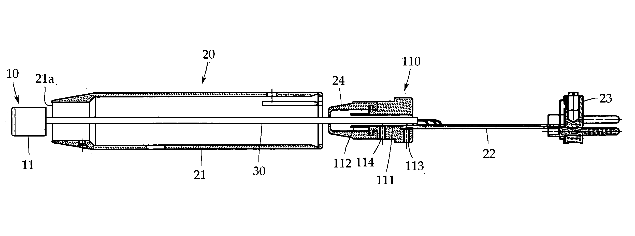
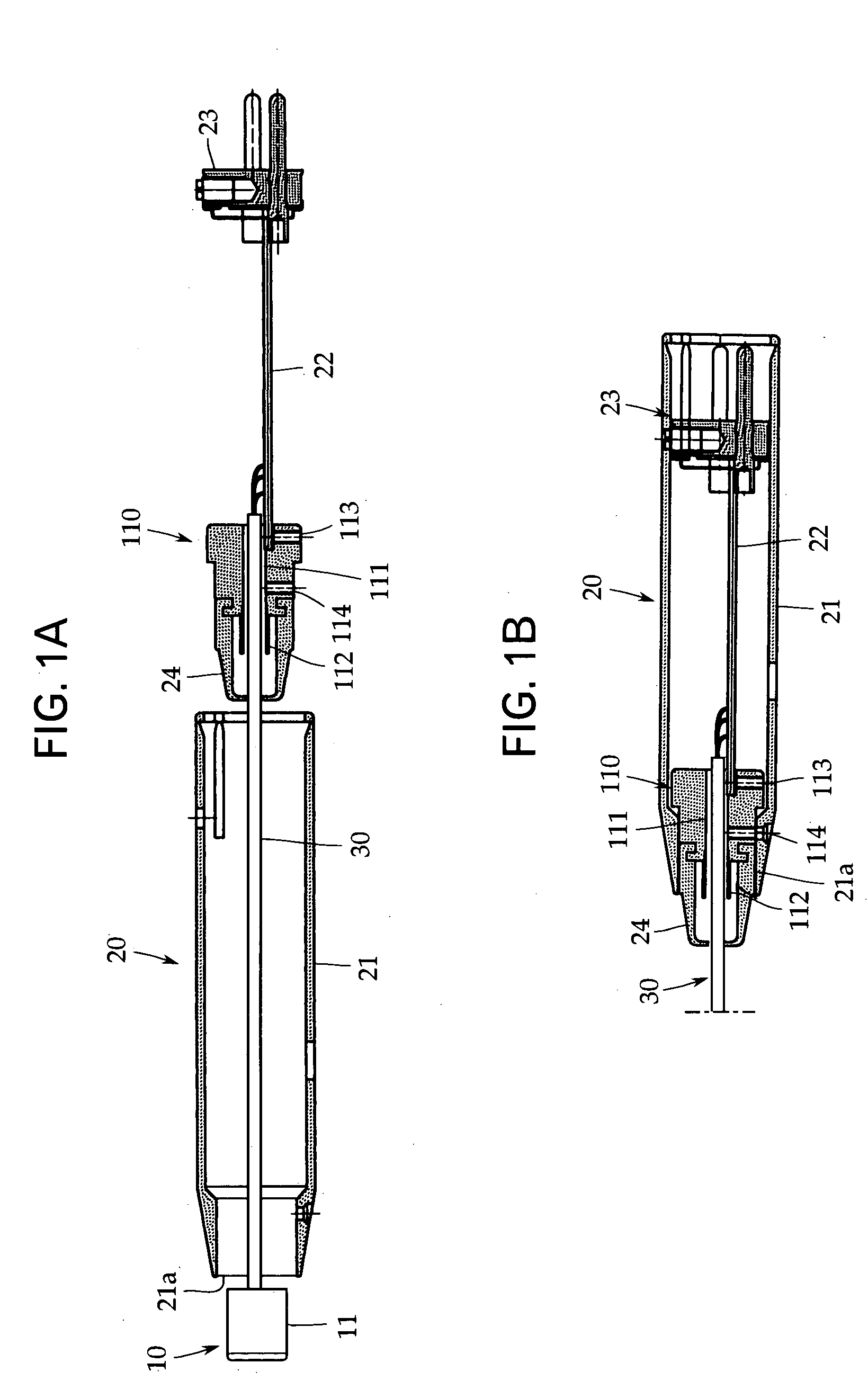
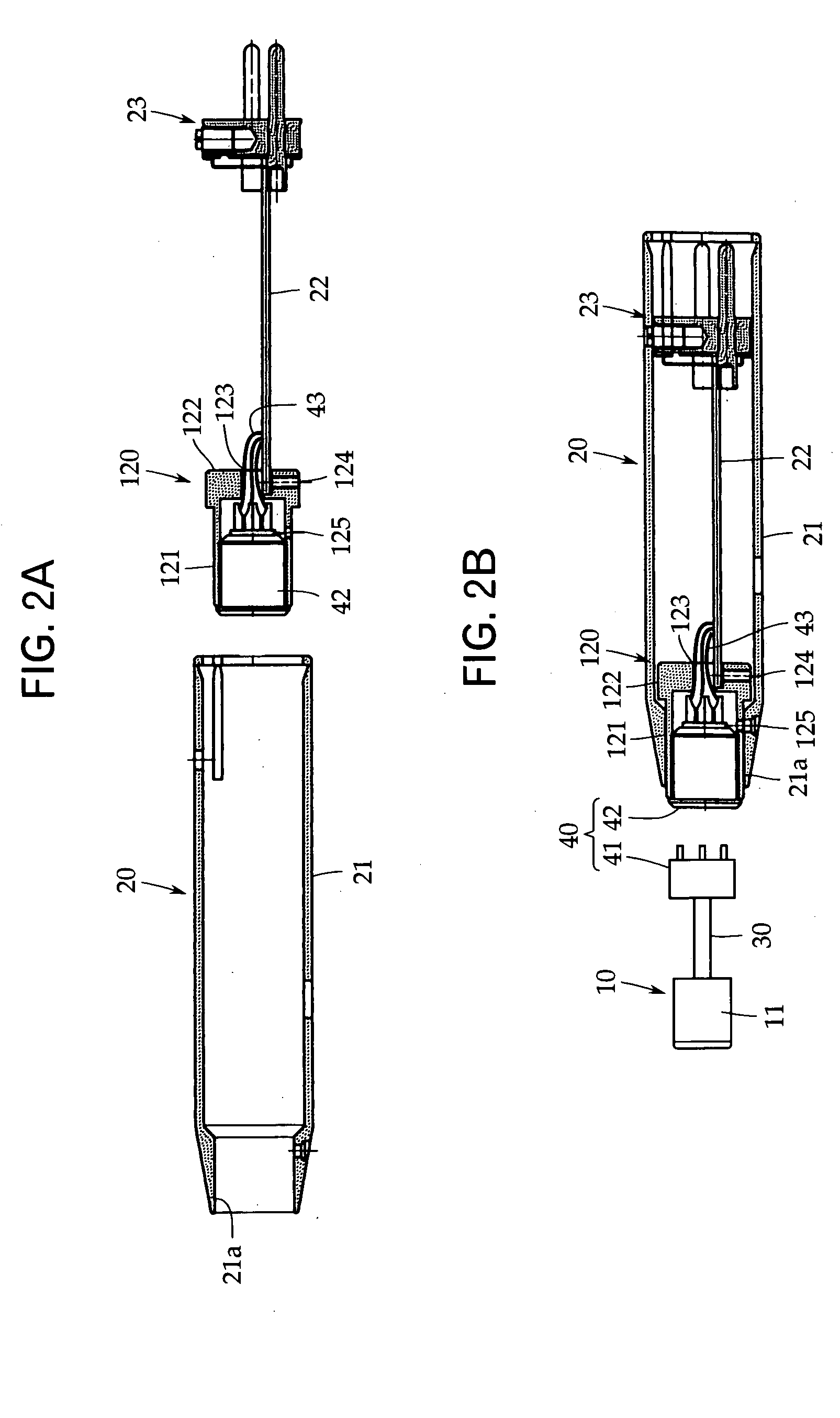
[0039] Referring to FIGS. 1 to 3, embodiments of the present invention will be discussed below. The present invention is not limited to these embodiments. FIGS. 1 and 2 show Embodiments 1 and 2 of a tie pin microphone and correspond to the foregoing conventional examples 1 and 2 shown in FIGS. 4 and 5. FIG. 3 shows Embodiment 3 of a gooseneck microphone and corresponds to the foregoing conventional example 3 shown in FIG. 6.

[0040] In the explanation of Embodiments 1 to 3, constituent elements not to be particularly changed from conventional examples 1 to 3 are indicated by the same reference numerals. FIGS. 1A to 3A are exploded views showing that an output module section is being assembled. FIGS. 1B to 3B are sectional views showing the completion of the assembly of the output module section.

[0041] In Embodiment 1 of FIG. 1, a condenser microphone is a tie pin microphone similar to conventional example 1 of FIG. 4, in which the condenser microphone unit 10 and the output module s...


PUM


Abstract

In a condenser microphone including a microphone unit and an output module section which are connected to each other via a microphone code, the length of a microphone code in the output module section is shortened without interfering with soldering of the microphone code to a circuit board of the output module section, so that noise caused by electromagnetic waves is prevented. In a condenser microphone where a condenser microphone unit 10 and an output module section 20, in which a circuit board 22 is housed in a shield case 21, are connected to each other via a microphone code 30, a connection metal part 110 of the microphone code and an output connector 23 are fixed to the circuit board 22 which can be inserted and removed in and from the shield case 21, the connection metal part 110 being detachably fit into an end opening 21a of the shield case 21. The connection metal part 110 of the microphone code can be removed from the shield case 21 together with the circuit board 22.

Description

TECHNICAL FIELD [0001] The present invention relates to a condenser microphone in which a condenser microphone unit and an output module section are connected to each other via a dedicated microphone code, and more specifically, to a technique for preventing high-frequency current from being generated by external electromagnetic waves in the output module section. BACKGROUND ART [0002] Various kinds of condenser microphones are available for various application purposes. The condenser microphones include a tie pin microphone attached to clothes or the like and a gooseneck microphone which is mainly used for conferences and disclosed in Patent Document 1 (Japanese Patent Application Publication No. H09-229292). [0003]FIGS. 4 and 5 show conventional examples 1 and 2 of a tie pin microphone. FIG. 6 shows conventional example 3 of a gooseneck microphone. Of these drawings, FIGS. 4A and 5A are exploded views showing that an output module section is being assembled. FIGS. 4B and 5B are se...

Claims


Application Information

Patent Timeline
IPC IPC(8): H04R25/00
CPCH04R31/006H04R19/04
Inventor AKINO, HIROSHI
Owner AUDIO-TECHNICA
Why Eureka
Try Eureka