Cutting device

a cutting device and reaming technology, applied in the field of cutting or reaming devices, can solve the problems of slow and tedious surgery, difficult cutting of bones, and only slightly more rigid guide rods, so as to facilitate the more rapid connection of cutters and facilitate the more rapid exchanging of cutters

Inactive Publication Date: 2006-01-19
PEPPER JOHN R
View PDF25 Cites 140 Cited by
  • Summary
  • Abstract
  • Description
  • Claims
  • Application Information

AI Technical Summary

Benefits of technology

[0016] It is another object of the present invention to facilitate the more rapid exchanging of cutters during the bone reaming process.
[0017] It is a further object of the present invention to provide a cutter that facilitates the connection of the cutter to a guide rod.
[0018] It is a yet another object of the present invention to provide a cutter that facilitates the more rapid connection of the cutter to the guide rod.

Problems solved by technology

Bone is difficult to cut, especially in young males, who are frequently the fracture patient.
This is a slow and tedious part of the surgery.
The difficulty arises in that the guide rod is very long and is only slightly more rigid than a coat hanger.
The flexible shaft is also pretty flimsy and almost as long.
The guide rod's long length outside the body makes it a hard target for connection with the cutter and the flexible shaft.
This connection is further complicated because the surgeon's gloves are wet with blood and fat from the canal, rendering them very slick.
This provides additional difficulty in manipulating the cutter or reamer heads onto the guide rod by requiring the drill and drill head to be lifted high into the air to perform the connection or exchange.
This is further complicated by the fact that if the reamer head is dropped from the hand onto the floor during this process, it must be sterilized delaying the surgical procedure even further.
Clearly, reaming is a frustrating part of the long bone fracture fixation procedure, and it is no wonder it is left to residents and those in their medical training to do this tedious task.

Method used


Image

  • Cutting device
  • Cutting device
  • Cutting device

Examples


Embodiment Construction

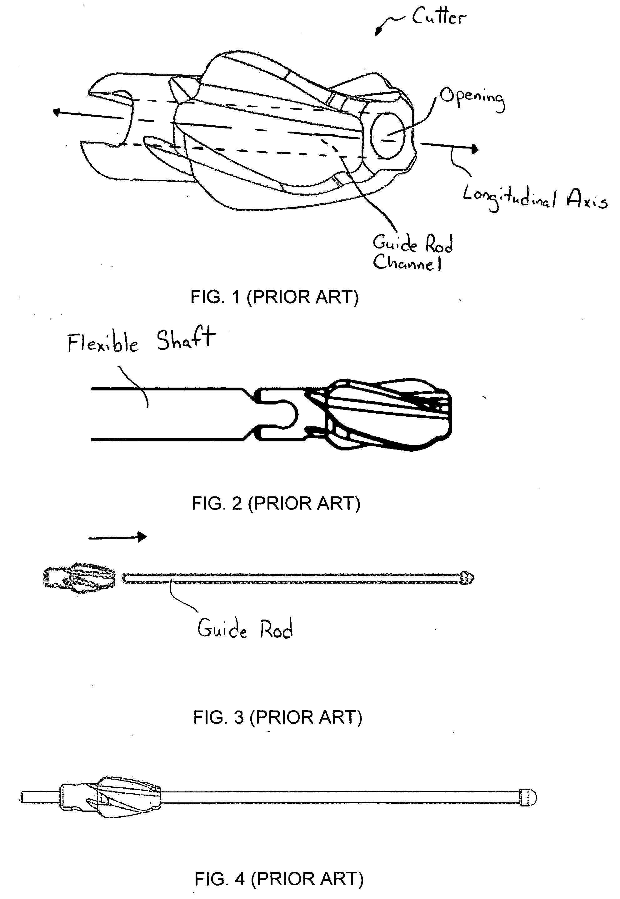
[0054] Referring to the drawings, and in particular FIGS. 1 through 4, a prior art cutter is shown, as well as the prior art method of connecting or loading the cutter with a guide rod. A guide rod bore or channel of the prior art cutter is along the longitudinal axis of the cutter and defines an opening that is perpendicular to the longitudinal axis.

[0055] In order to connect the prior art cutter with the guide rod, the surgeon must align the guide rod along the longitudinal axis of the cutter and insert it through the opening. The cutter then travels along the guide rod, which is disposed through the guide rod channel of the cutter. During the surgical procedure, this is a difficult task at best, especially due to the tight tolerance between the central bore in the reamer and the outer surface of the guide rod.

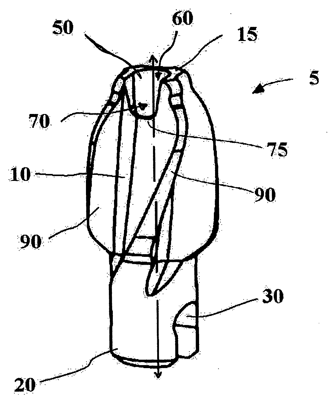
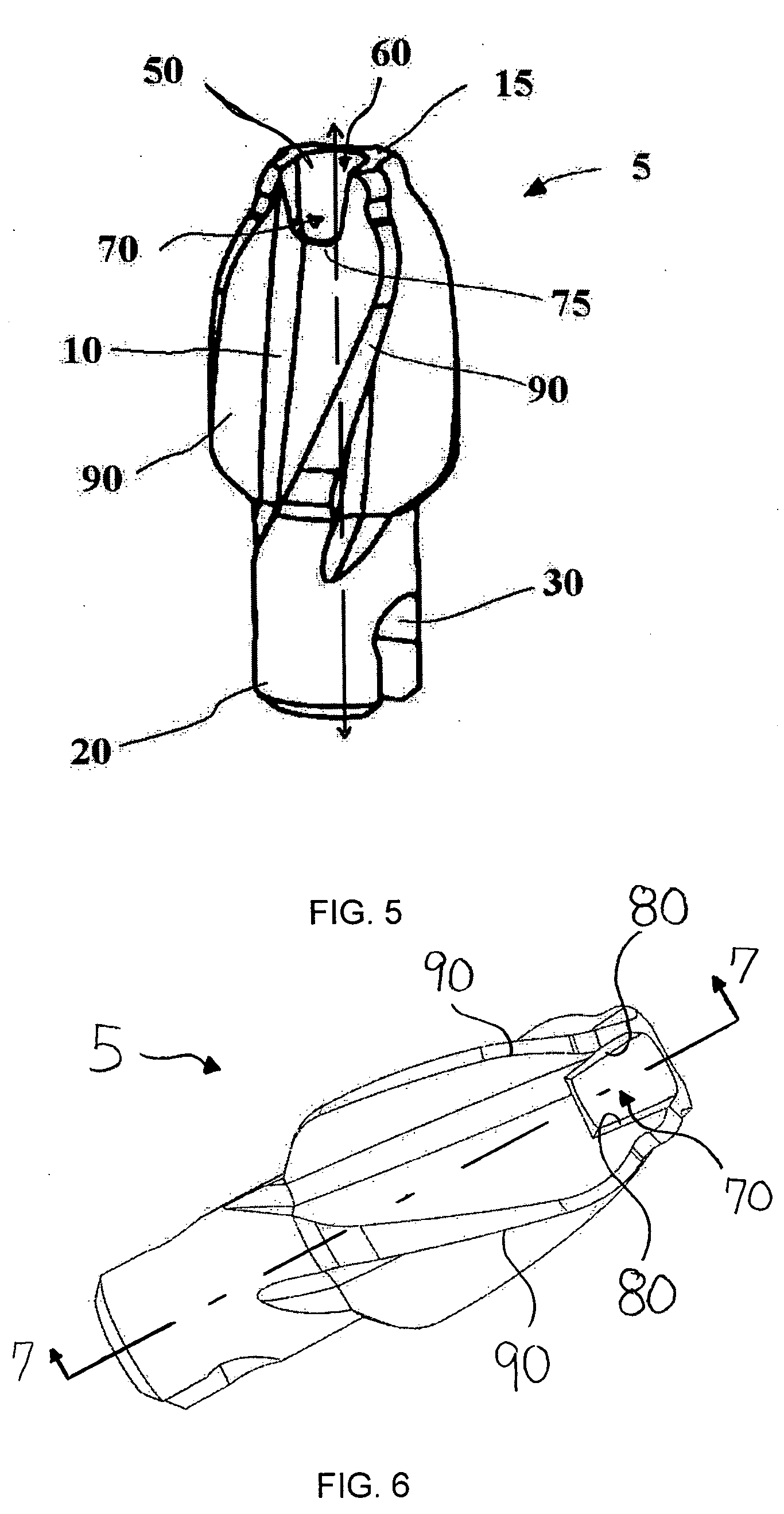
[0056] Referring to FIGS. 5 through 10, a cutter of the present invention is shown and generally represented by reference numeral 5. Cutter 5 has a body 10 with a distal e...


PUM


Abstract

A cutter for reaming of the bone canal is provided. The cutter facilitates connection with a guide rod by having a larger target for insertion of the guide rod into the cutter channel of the cutter. The cutter can have an opening with a first portion that is substantially orthogonal to the longitudinal axis of the cutter channel and a second portion that is non-orthogonal to the longitudinal axis. The first and second portions can be orthogonal to each other.

Description

BACKGROUND OF THE INVENTION [0001] 1. Field of the Invention [0002] The present invention relates to bone canal reaming devices and methods. More particularly, the present invention relates to a cutting or reaming device usable with a guide rod. [0003] 2. Description of Related Art [0004] The treatment of long bone fractures typically involves internal stabilization. An intramedullary nail or rod, which is typically a cylindrical hollow rod, is inserted in the center of the intramedullary canal or marrow cavity. The rod, which is typically titanium alloy or stainless steel, is strong enough to support the bone loads during the bones healing process. The bones that are fixed in this manner are the femur, tibia, humerus, radius and ulna. Nails are typically generally circular in cross section or have a shape nearly circular. [0005] One step in the surgical technique is the preparation of the canal. The bone canal varies in shape depending upon the position along the bone axis. The cen...

Claims


Application Information

Patent Timeline
Patent Type & Authority Applications(United States)
IPC IPC(8): A61B17/00
CPCA61B17/164A61B17/1615
Inventor PEPPER, JOHN R.
Owner PEPPER JOHN R
Why Eureka
Try Eureka