

Joint structure of robot
a joint structure and robot technology, applied in the field of robot joint structure, can solve the problems of unlikely interference between the cover covering the first main link and the cover covering the second main link, and achieve the effect of increasing the critical value of the rotational speed and minimizing the reduction of the movable rang
- Summary
- Abstract
- Description
- Claims
- Application Information
AI Technical Summary
Benefits of technology
Problems solved by technology
Method used
Image

Examples
first embodiment
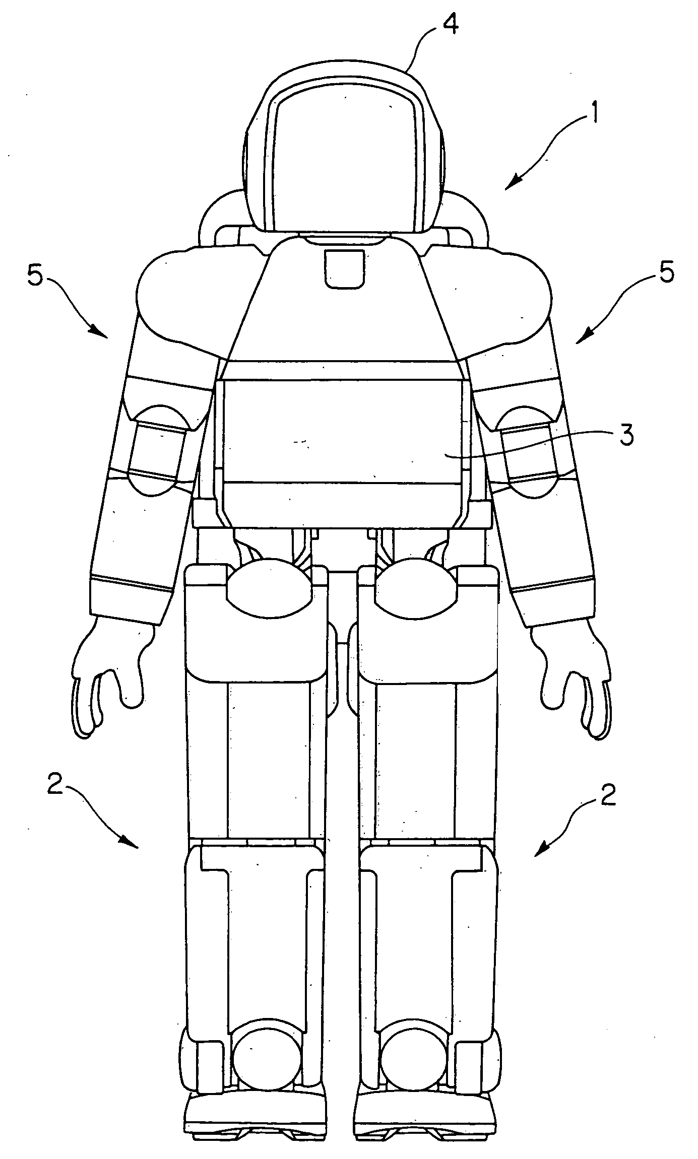
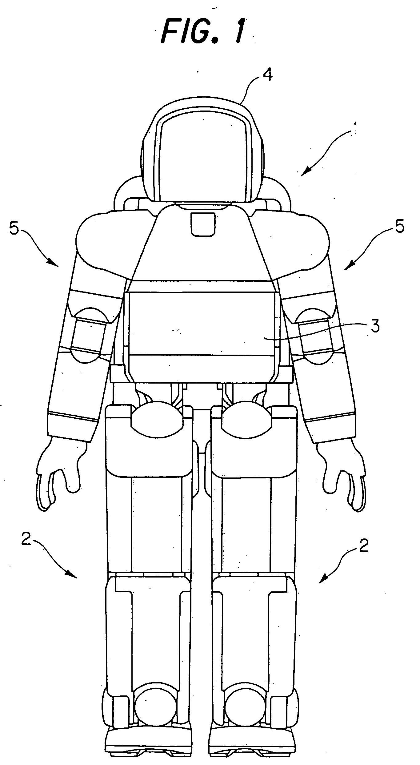
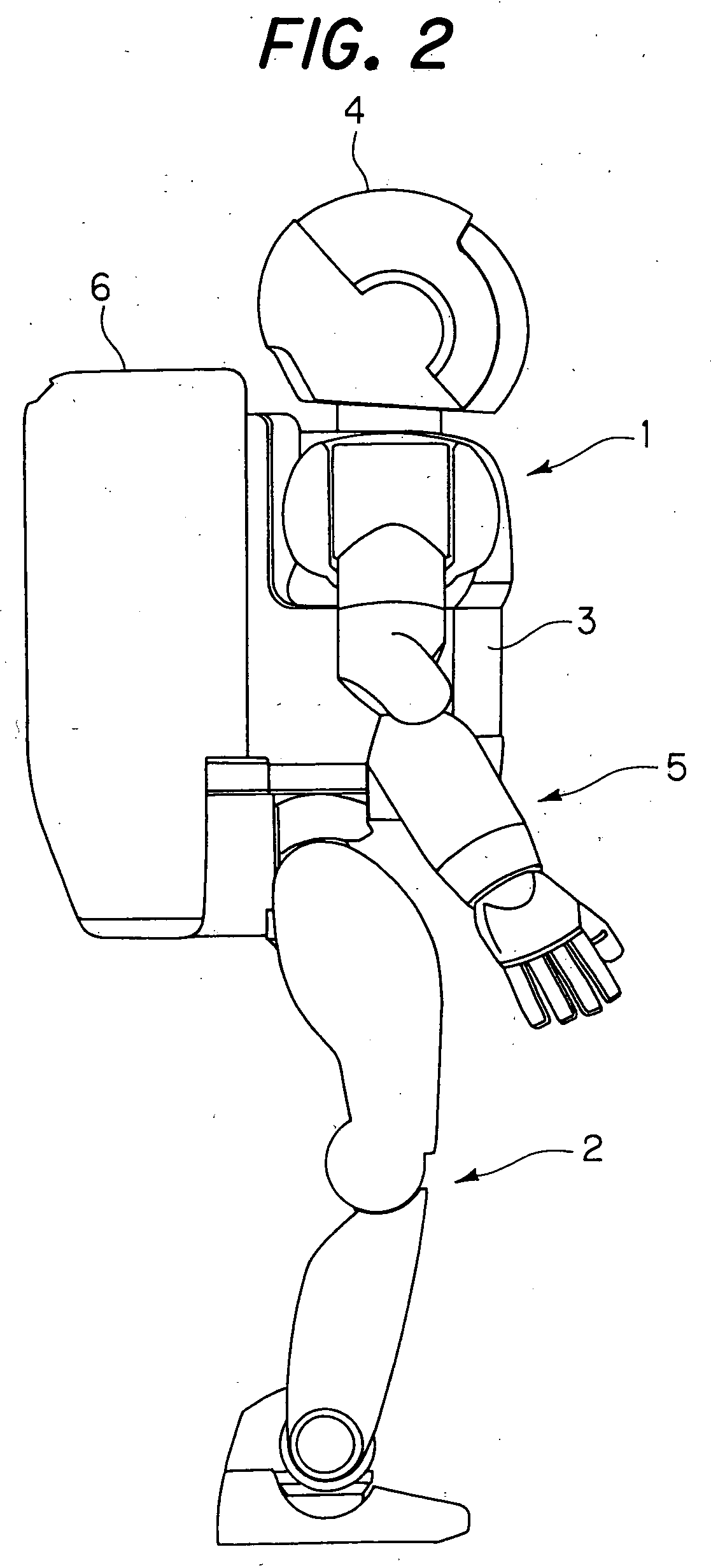
[0048]FIG. 1 is a front view of the robot and FIG. 2 is right side view thereof.
[0049] As shown in FIG. 1, the robot 1 is equipped with a pair of leg linkages 2 and an upper body (main unit) 3 above the leg linkages 2. A head 4 is formed on the upper end of the upper body 3 and two arm linkages 5 are connected to opposite sides of the upper body 3. As shown in FIG. 2, a housing unit 6 is mounted on the back of the upper body 3 for accommodating therein, inter alia, an electronic control unit and a power supply battery. The robot 1 shown in FIGS. 1 and 2 is equipped with covers for protecting its internal structures.
[0050]FIG. 3 is an explanatory view showing a skeletonized view of the robot 1. The number and locations of the joints will be explained with reference to this drawing. As illustrated, the left and right leg linkages 2 of the robot 1 are each equipped with six joints and the arm linkages 5 are equipped with five joints.
[0051] In the leg linkages 2, the six joints compr...
second embodiment
[0100] the invention to be explained in the following is therefore configured to increase the range of motion of the joints while preventing interference between the links and covers.
[0101] A robot joint structure according to the second embodiment of the invention will now be explained.
[0102]FIG. 16 is a plan view, similar to FIG. 7, but showing a robot joint structure according to the second embodiment of the invention.
[0103] An explanation will be made focusing on the points of difference from the first embodiment. As illustrated, in the second embodiment a second movable link 72a is curved in the shape of an archery bow, θAB is defined as −15.5 degrees, and θCD is defined as 30 degrees.
[0104] FIGS. 17 to 19 are plan views showing driven states of the elbow joint 36 shown in FIG. 16. Note that FIG. 17 shows the elbow joint 36 when θ1 is 24 degrees and θ2 is 25.7 degrees, i.e., when θ1+θ2 is 49.7 degrees, and FIG. 18 shows the elbow joint 36 when θ1 is 45 degrees and θ2 is 55 d...
third embodiment
[0112] A robot joint structure according to the invention will be explained next.
[0113]FIG. 22 is a plan view similar to FIG. 16 showing a robot joint structure according to the third embodiment of the invention.
[0114] An explanation will be made focusing on the points of difference from the first and second embodiments. In the third embodiment, the joint structure is provided with a mechanical over-rotation prevention mechanism for prevention over-rotation (excessive driving) of the elbow joint 36.
[0115] As shown in FIG. 22, a pin 90 is provided on the first movable link 70 such that the pin 90 is inserted into an arcuate hole 94 formed in a stopper 92. The stopper 92 is fastened to the upper arm first plate 42a (not shown).
[0116] The hole 94 is formed to have the same arcuate shape as the locus the pin 90 describes when the first movable link 70 is driven. One terminal end 94a of the hole 94 is defined so that, when the elbow joint 36 is driven, the rotation of the first movabl...
PUM
 Abstract
Description
Claims
Application Information