
Fuel injector and a method of sealing the same

a fuel injector and injector technology, applied in the direction of fuel injection apparatus, spraying apparatus, charge feed system, etc., can solve the problem of impaired operation characteristics of the fuel injector 210, and achieve the effect of simplifying the sealing structur

Inactive Publication Date: 2006-01-26
AISAN IND CO LTD
View PDF0 Cites 14 Cited by
  • Summary
  • Abstract
  • Description
  • Claims
  • Application Information

AI Technical Summary

Benefits of technology

[0018] Accordingly, it is an object of the present invention to provide a fuel injector and a method of sealing the same, in which the maximum outside diameter of the body of the fuel injector can be reduced and the sealing structure can be made simpler.
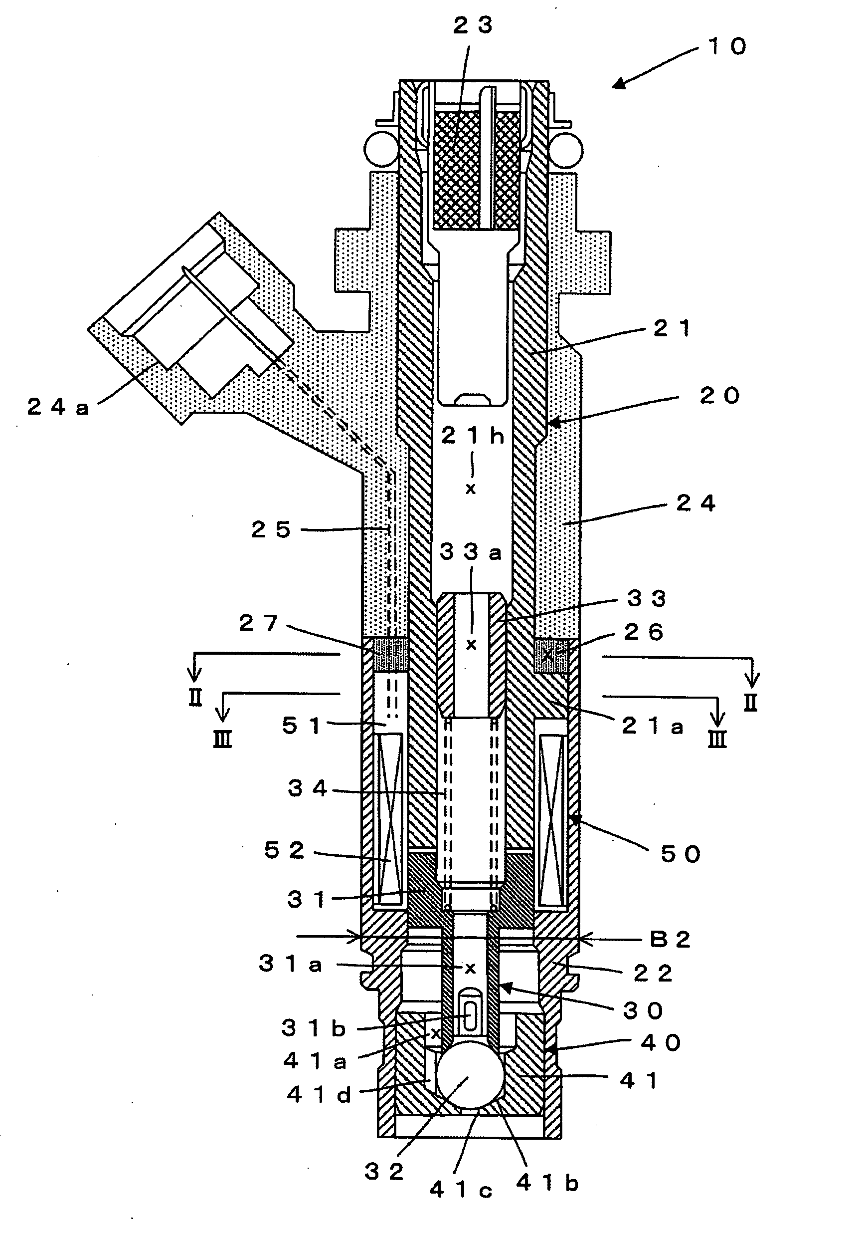
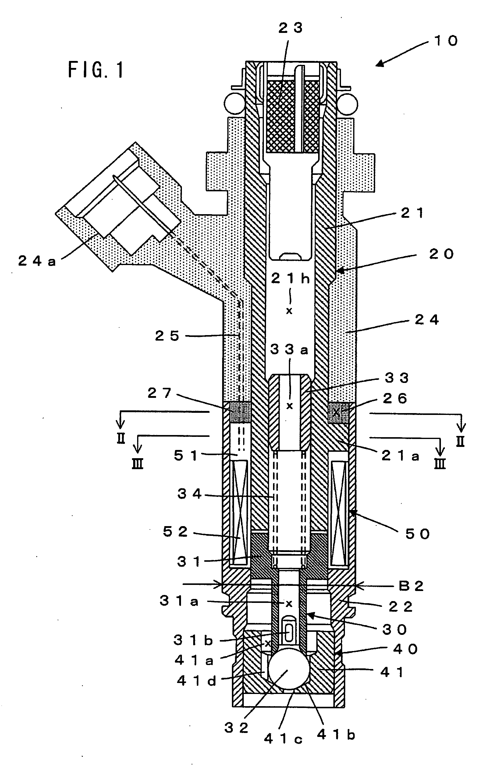
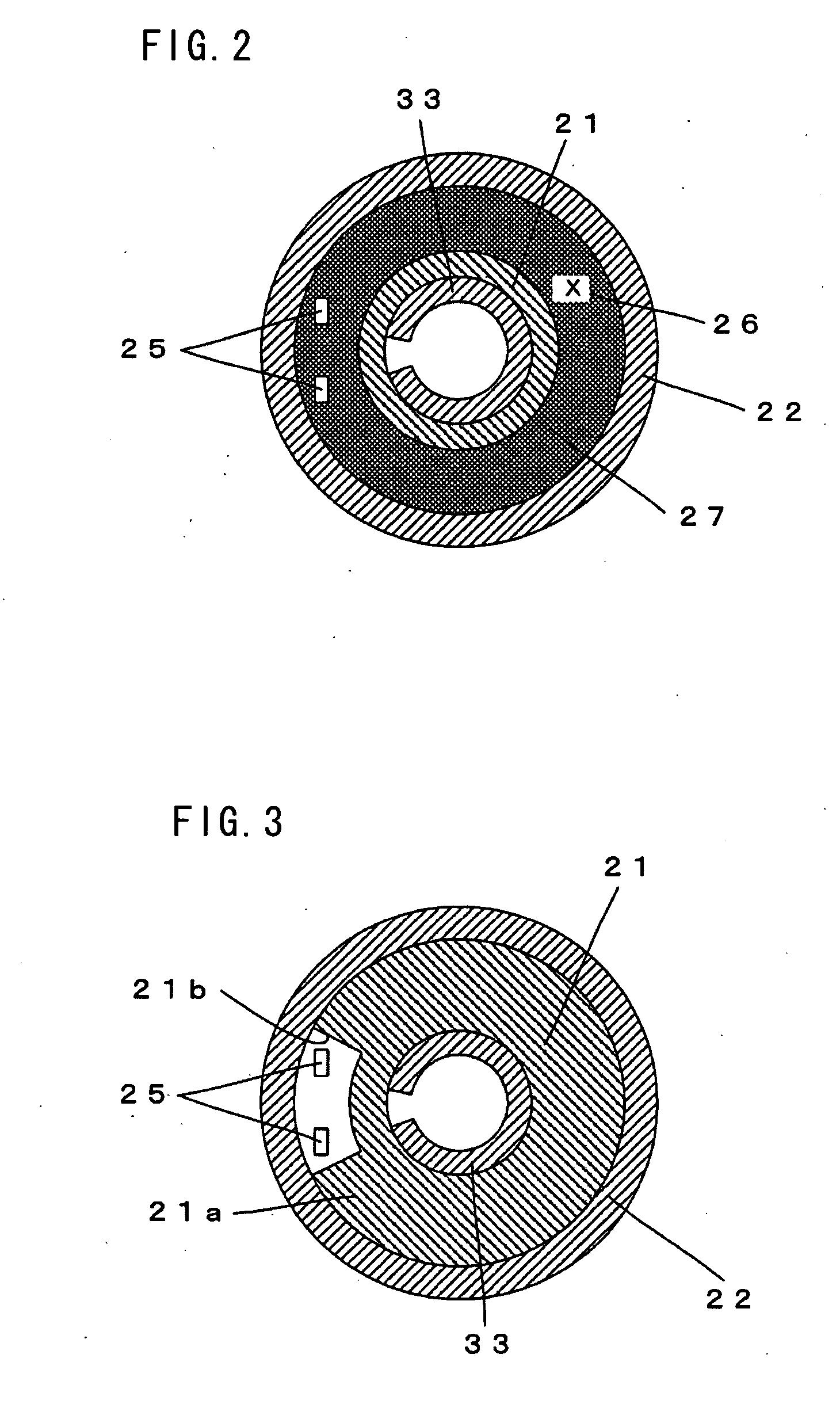
[0019] In one aspect of the invention, a seal is provided in a region that is surrounded by a fixed core, a body and a connector, in the state in which a connecting wire is connected to a coil and runs through the region. Thus, it is not necessary to provide a seal in a flange of the fixed core. Therefore, the outside diameter of the flange of the fixed core, or the outside diameter of a portion of the body which contacts the flange (the maximum outside diameter of the body), can be reduced.
[0022] In another aspect of the invention, a seal is provided in a region that is surrounded by the body and the connector, in the state in which the connecting wire is connected to the coil and runs through the region. In this manner, too, it is not necessary to provide a seal in the flange of the fixed core. Therefore, the outside diameter of the flange of the fixed core, or the outside diameter of a portion of the body which contacts the flange (the maximum outside diameter of the body), can be reduced.
[0025] In another aspect of the invention, the maximum outside diameter of the body of the fuel injector is smaller than the minimum inside diameter of a mounting hole of an intake manifold. In this case, the greater part of the body of the fuel injector can be inserted into the mounting hole of the intake manifold. Therefore, the length of the movable core of the fuel injector can be shortened, so that the operating characteristics of the fuel injector can be improved. Further, the coil is cooled by the intake air within the intake manifold, so that the operating characteristics of the fuel injector 10 is stabilized.

Problems solved by technology

However, the movable core 230 increases in weight as it increases in length, so that the operating characteristics of the fuel injector 210 is impaired.

Method used


Image

  • Fuel injector and a method of sealing the same
  • Fuel injector and a method of sealing the same
  • Fuel injector and a method of sealing the same

Examples


Embodiment Construction

[0038] According to the present invention, a representative fuel injector may includes a fixed core, a movable core that can move with respect to the fixed core, a coil holding element that is disposed around the fixed core, a connector that is disposed around the fixed core and in which a connecting wire is embedded, the connecting wire being connected to the coil on the coil holding element, and a body that is disposed around the coil holding element.

[0039] Typically, the fixed core has a radially outwardly protruding flange. The coil holding element is disposed on the downstream side of the flange of the fixed core with respect to the direction of fuel flow. Further, the connector is formed of resin.

[0040] In one embodiment of the present invention, a seal is provided in a region that is surrounded by the fixed core, the body and the connector, with the connecting wire running through the region. Specifically, in this embodiment, the connecting wire that is connected to the coi...


PUM


Abstract

A movable core 31 can move with respect to a fixed core 21. A bobbin 51 on which a coil 52 is wound is disposed around the fixed core 21. A body 22 is disposed around the bobbin 51. A connector 24 is formed of resin and disposed around the fixed core 21. A connecting wire 25 is connected to the coil 52 and embedded in the connector 24. A seal 27 is disposed in a region 26 that is surrounded by the fixed core 21, the connector 24 and the body 22, with the connecting wire 25 running through the seal 27.

Description

BACKGROUND OF THE INVENTION [0001] 1. Field of the Invention [0002] The present invention relates to fuel injectors for internal combustion engines and a method of sealing the same. [0003] 2. Description of the Related Art [0004] Typically, electromagnetic fuel injectors are used as fuel injectors for internal combustion engines. [0005] An example of a known electromagnetic fuel injector is disclosed in Japanese non-examined laid-open patent publication No. 6-50235 and is reproduced in FIG. 10, which shows a sectional view of a fuel injector 210. [0006] The fuel injector 210 includes a fixed core 221, a movable core 230, a bobbin 251 and a body 270. A coil 252 is wound on the bobbin 251 and develops electromagnetic force for driving the movable core 230. A fuel injector of this type is provided with a seal for preventing fuel from leaking to the outside. For example, a seal is provided in order to prevent fuel from leaking to the outside via a connecting wire 225 for supplying elect...

Claims


Application Information

Patent Timeline
Patent Type & Authority Applications(United States)
IPC IPC(8): F02M57/04
CPCF02M51/005F02M51/0671F02M61/145F02M2200/90F02M69/042F02M2200/8061F02M2200/858F02M61/168
Inventor AOKI, TSUNEAKITATSUKAWA, MASAMIMAKIMURA, TOSHIRO
Owner AISAN IND CO LTD
Learn More