Device for preventing backflow in a cooling system

Inactive Publication Date: 2006-01-26
IBM CORP
View PDF8 Cites 27 Cited by
  • Summary
  • Abstract
  • Description
  • Claims
  • Application Information

AI Technical Summary

Benefits of technology

[0007] It is, therefore, a principle object of this invention t

Problems solved by technology

One problem with this type fan configuration is that when one fan fails, the pressure difference across the surviving fan pushes air backwards through the failed fan.
This reduces the delivered flow rate that would otherwise be available from the surviving fan(s), a significant fraction of the overal

Method used


Image

  • Device for preventing backflow in a cooling system
  • Device for preventing backflow in a cooling system
  • Device for preventing backflow in a cooling system

Examples


Example

[0017] The invention will now be described in more detail by way of example with reference to the embodiments shown in the accompanying figures. It should be kept in mind that the following described embodiments are only presented by way of example and should not be construed as limiting the inventive concept to any particular physical configuration.

[0018] Further, if used and unless otherwise stated, the terms “upper,”“lower,”“front,”“back,”“over,”“under,” and similar such terms are not to be construed as limiting the invention to a particular orientation. Instead, these terms are used only on a relative basis.

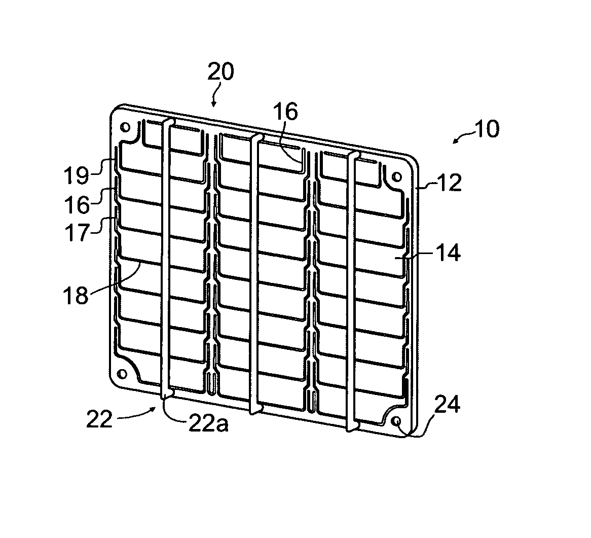
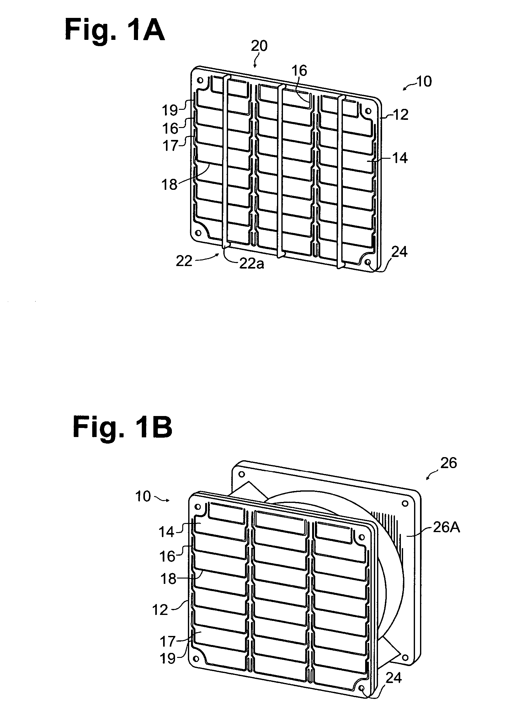
[0019] With reference now to the figures, and in particular with reference to FIG. 1A, there is depicted a rear view of the fan valve 10 of the present invention. The fan valve 10 is formed of a thin flat flexible plate 12. The plate 12 is generally some type of plastic or film material. A plurality of flaps 14 are formed in the plate 12. The flaps 14 are formed so as to al...


PUM


Abstract

A novel check valve for an exhaust device is formed from a thin flexible plate. A plurality of flaps is formed in the thin flexible plate. The flaps are arranged in a vertical manner to form at least one column of flaps. A stopper is coupled to a back side of the thin flexible plate. The stopper prevents the plurality of flaps from moving towards the stopper.

Description

BACKGROUND OF THE INVENTION [0001] 1. Field of the Invention [0002] The present invention relates generally to a device for preventing backflow in a cooling system, and more particularly, to a fan check valve having a plurality of flaps, wherein the flaps control airflow in a single direction. [0003] 2. Background Information [0004] Enclosed electronic systems, which run on continuous operation, generally employ a system for cooling the enclosure. Most cooling systems typically employ some type of fan or blower. Many cooling systems employ redundant fans that are arranged in parallel. This arrangement is used to guard against catastrophic loss of cooling flow in the event of a single fan device failure. One problem with this type fan configuration is that when one fan fails, the pressure difference across the surviving fan pushes air backwards through the failed fan. This reduces the delivered flow rate that would otherwise be available from the surviving fan(s), a significant fract...

Claims


Application Information

Patent Timeline
IPC IPC(8): F16K15/16
CPCF16K15/031H05K7/20172F16K15/035F04D25/14Y10T137/784
Inventor BERENS, JESSICA ROSEHUETTNER, CARY MICHAELGOOD, MICHAEL SCOTTHOLAHAN, MAURICE FRANCIS
Owner IBM CORP
Why Eureka
Try Eureka