
Double-acting device for generating synthetic jets

a technology of synthetic jets and actuators, which is applied in the direction of indirect heat exchangers, machines/engines, lighting and heating apparatus, etc., can solve the problems of restricting the application of conventional fluids, and achieve the effect of enhancing the vortex train

Active Publication Date: 2006-01-26
NAT TAIWAN UNIV
View PDF8 Cites 24 Cited by
  • Summary
  • Abstract
  • Description
  • Claims
  • Application Information

AI Technical Summary

Benefits of technology

[0036] Preferably, a mutual interaction of the antiphasely oscillating jets is induced by a defined arrangement of the at least two output elements to enhance the train of vortices.

Problems solved by technology

This may further restrict the application of the conventional fluid in the small-scale system as a result.

Method used


Image

  • Double-acting device for generating synthetic jets
  • Double-acting device for generating synthetic jets
  • Double-acting device for generating synthetic jets

Examples


first embodiment

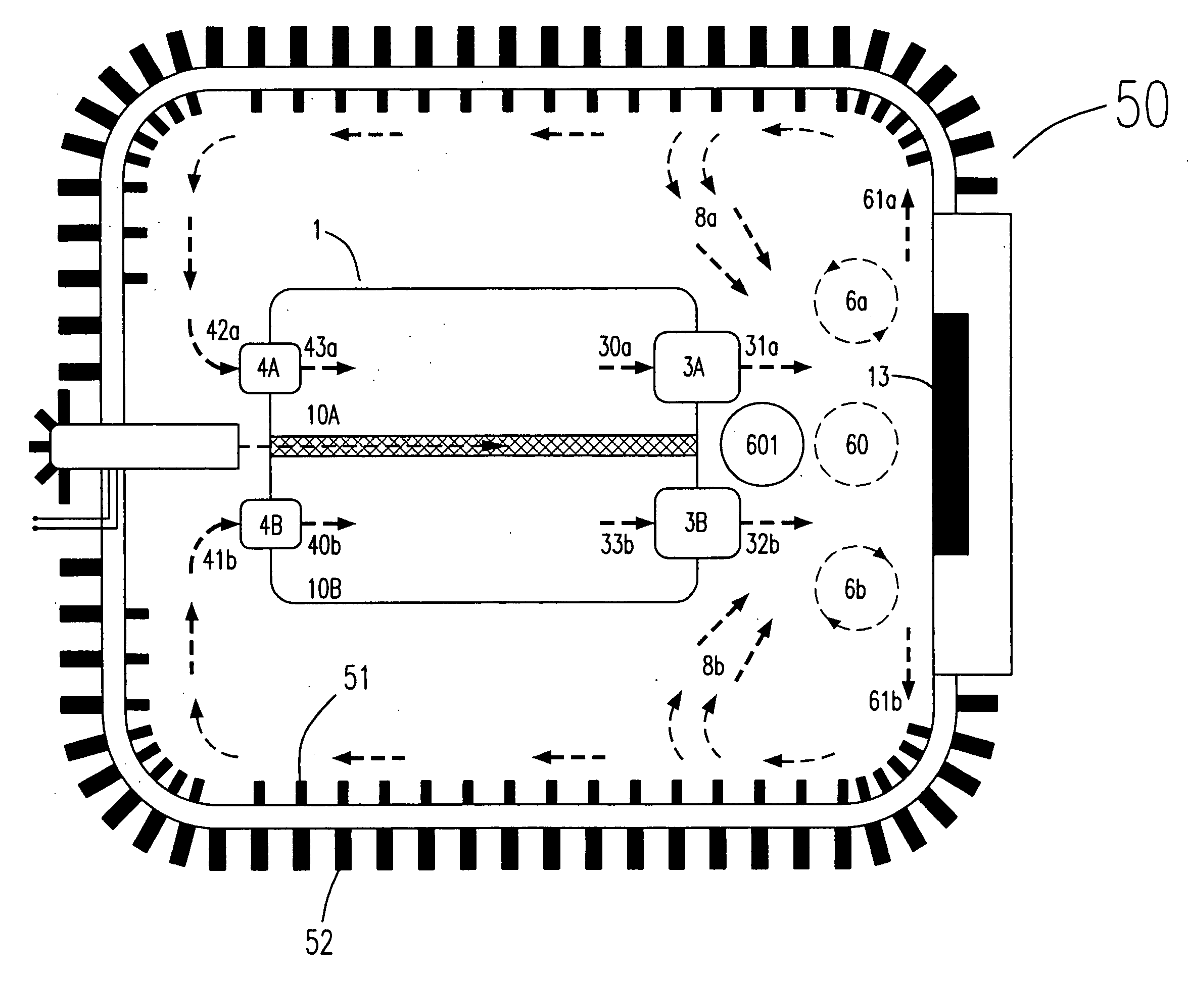
[0051] Please refer to FIGS. 2(a) to 2(c), which illustrate the structures of the double-acting device according to the present invention. The double-acting device 1 of the present invention includes a sealed chamber 10 and a diaphragm 12 located therein to bisect the chamber 10 into two sub-chambers 10A and 10B. The input elements 4A and the output element 3A, and the input elements 3A and the output element 3B are respectively configured on the wall 11 of the sub-chamber 10A and 10B for respectively forming an input system 4 and an output system 3. Accordingly, the output elements 3A and 3B, and the input elements 4A and 4B are respectively arranged in two paired arrangements. A control circuit 2 is configured inside the chamber 10 to drive the diaphragm 12 and the electricity needed is provided by the power supply 20.

[0052] Please refer to FIG. 2(b). The diaphragm 12 driven by the control circuit 2 acts in a direction toward to the sub-chamber 10A, i.e. during the U direction, in...

third embodiment

[0062] Please refer to FIGS. 6(a) and 6(b), which illustrate the structure of the double-acting device for generating synthetic jets according to the present invention. Compared with the forgoing embodiments, is the difference therebetween are the structure of the double-acting device 1 and, accordingly, the arrangements of the sub-chambers 10A and 10B, the output elements 3A and 3B, and the input element 4B. As shown in FIGS. 6(a) and 6(b), the double-acting device 1 has an axisymmetric structure with the symmetric axis 9, and the output elements 3A and 3B are axisymmetrically arranged relative to the symmetric axis 9. The action and function of the fluid 30a, 31a, 30b, 31b, 40b, 41b, 32a, 33a, 32b, 33b, 42b and 43b, and the vortices 60 in the double-acting device 1 according to this embodiment are respectively similar to those according to the above embodiments as shown in FIGS. 2(b) and 2(c), no matter the double-acting device 1 is during the up-stroke, i.e. the diaphragm 12 acts...


PUM


Abstract

A double-acting device for generating a synthetic jet is provided. The double-acting device includes a chamber having a cavity for a working fluid, a separating element for dividing the chamber into at least two sub-chambers, a control system connected to the chamber for controlling the separating element to act reciprocatingly, an input system connected to the chamber for inputting the working fluid to the chamber therethrough and an output system connected to the chamber for outputting the working fluid from the chamber therethrough. When the working fluid is pushed and pulled by a reciprocating action of the separating element, a train of vortices would be puffed and a non-zero-net-mass-flux fluid is generated through a designed structure and a defined arrangement of the input system and the output system.

Description

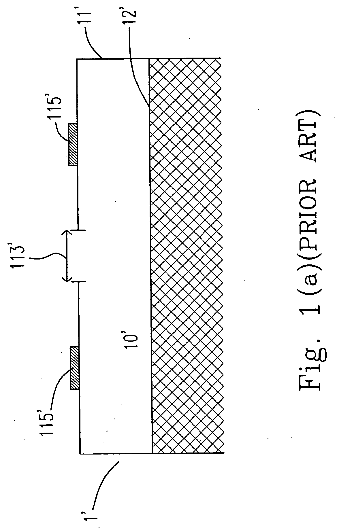
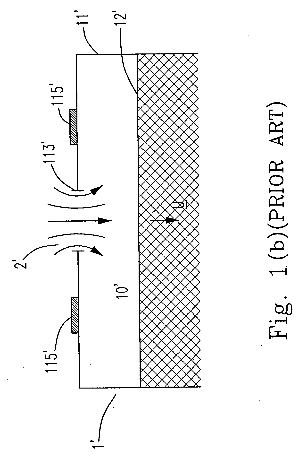
FIELD OF THE INVENTION [0001] The present invention is related to a fluid actuator for generating synthetic jets, especially to the fluid actuator, which is applied to control the mixing of fluid flows and to control the fluid field and the fluid actuator, which is used in a cooling system. BACKGROUND OF THE INVENTION [0002] Conventional synthetic jets are periodic jets generated by pushing and pulling a fluid through an orifice of an actuator. While the actuator reciprocatingly acts, the fluid would be revolvingly oscillated, and be sucked into or jetted out from the actuator due to the pressure variation therein. Since the mass flux of the fluid sucked into the actuator is equal to that of the fluid jetted out, i.e. a time-mean mass flux of the oscillated fluid through this orifice is zero, the synthetic jets is so called as “Zero-Net-Mass-Flux jets” in early days. Other common expressions for such a generation of jets are “Suction and Blowing” and “Oscillatory Blowing”. [0003] Te...

Claims


Application Information

Patent Timeline
IPC IPC(8): H05K7/20
CPCF15D1/08
Inventor WANG, AN-BANGTRAVNICEK, ZDENEKWANG, YI-HUAHSU, MING-CHANG
Owner NAT TAIWAN UNIV
Learn More