
Radio frequency identification interrogation systems and methods of operating the same

a radio frequency identification and interrogation system technology, applied in the field of communication systems, can solve the problems that the technology is generally not compatible with the unit level counting of rfid objects, and achieve the effect of improving the quality of the reply cod

Inactive Publication Date: 2006-01-26
LONE STAR IP HLDG LP
View PDF99 Cites 144 Cited by
  • Summary
  • Abstract
  • Description
  • Claims
  • Application Information

AI Technical Summary

Benefits of technology

[0014] These and other problems are generally solved or circumvented, and technical advantages are generally achieved, by advantageous embodiments of the present invention which includes a reply code for a radio frequency identification (RFID) tag, a method of improving a reply code for a radio frequency identification (RFID) tag for interrogation by an interrogator and an RFID tag employing the same. In one embodiment, the reply code includes a preamble having information about a quality of a clock associated with the RFID tag. The reply code also includes a tag identification (ID) code providing a digital signature for the RFID tag. The reply code still further includes an aftamble located aft of the preamble and having information about the quality of the clock. The aftamble cooperates with the preamble to improve a quality of the reply code for interrogation by an interrogator.

Problems solved by technology

As with bar coding, the RFID techniques are primarily used for automatic data capture and, to date, the technologies are generally not compatible with the counting of RFID objects at the unit level.
While identification tags or labels may be able to survive the difficult conditions associated with medical applications, there is yet another challenge directed to attaching an identification element to any small device.
While manufacturers have multiple options for bonding, critical disparities between materials may exist in areas such as biocompatibility, bond strength, curing characteristics, flexibility and gap-filling capabilities.

Method used


Image

  • Radio frequency identification interrogation systems and methods of operating the same
  • Radio frequency identification interrogation systems and methods of operating the same
  • Radio frequency identification interrogation systems and methods of operating the same

Examples


Embodiment Construction

[0030] The making and using of the presently preferred embodiments are discussed in detail below. It should be appreciated, however, that the present invention provides many applicable inventive concepts that can be embodied in a wide variety of specific contexts. The specific embodiments discussed are merely illustrative of specific ways to make and use the invention, and do not limit the scope of the invention. The present invention will be described with respect to exemplary embodiments in a specific context, namely, RFID interrogation systems and methods of operating the same.

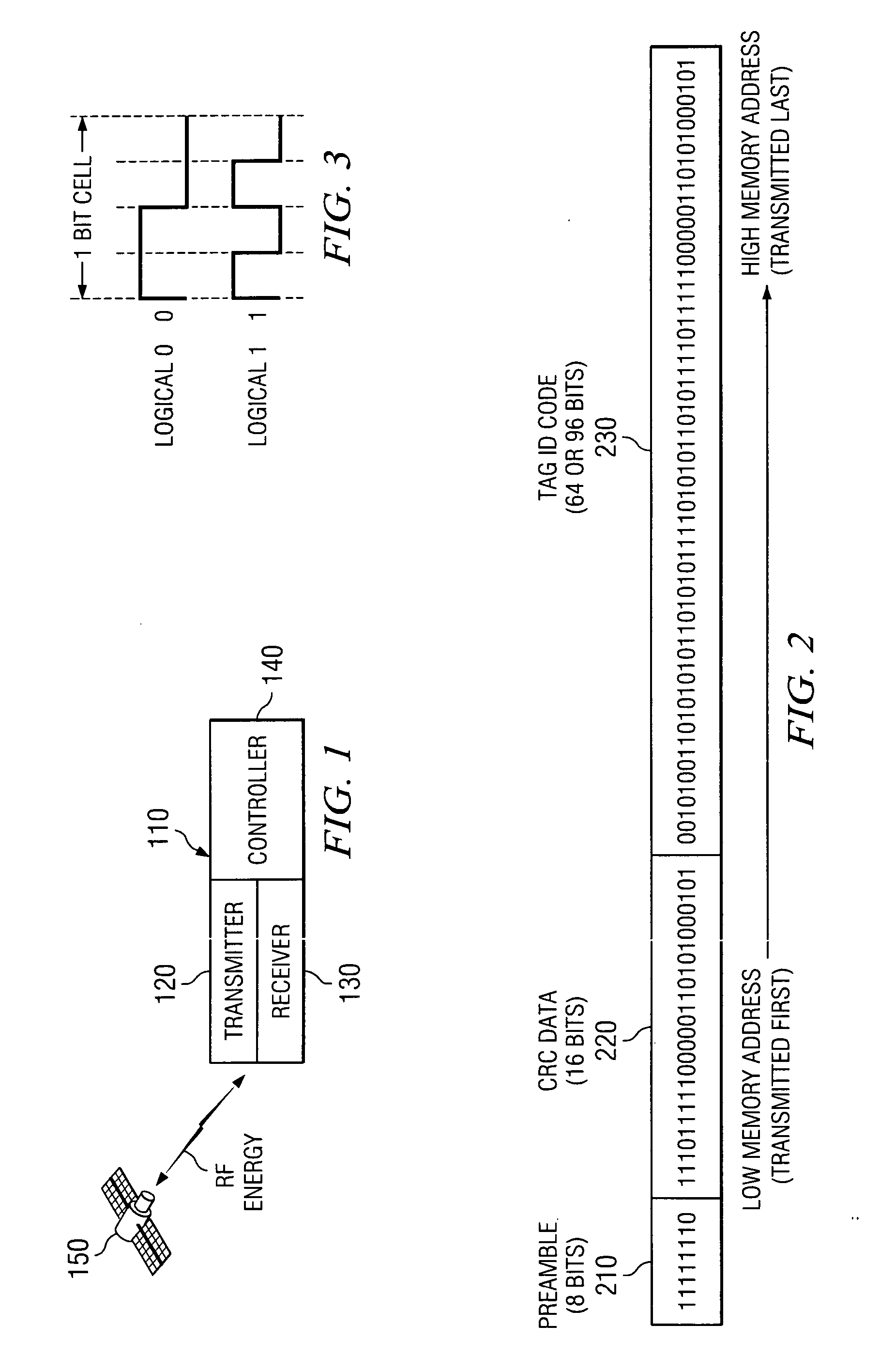
[0031] Referring initially to FIG. 1, illustrated is a diagram of an embodiment of an RFID interrogation system constructed in accordance with the principles of the present. The RFID interrogation system includes an interrogator 110 with a transmitter 120, a receiver 130, and a controller 140. The interrogator 110 energizes an RFID tag 150 and then receives the encoded radio frequency (RF) energy (reflecte...


PUM


Abstract

A reply code for a radio frequency identification (RFID) tag, a method of improving a reply code for a radio frequency identification (RFID) tag for interrogation by an interrogator and an RFID tag employing the same. In one embodiment, the reply code includes a preamble having information about a quality of a clock associated with the RFID tag. The reply code also includes a tag identification (ID) code providing a digital signature for the RFID tag. The reply code still further includes an aftamble located aft of the preamble and having information about the quality of the clock. The aftamble cooperates with the preamble to improve a quality of the reply code for interrogation by an interrogator.

Description

[0001] This application claims the benefit of U.S. Provisional Application No. 60 / 556,582, entitled “RFID Omnibus,” filed on Mar. 26, 2004, which is incorporated herein by reference.TECHNICAL FIELD [0002] The present invention is directed, in general, to communication systems and, more specifically, to radio frequency identification (RFID) interrogation systems and methods of operating the same. BACKGROUND [0003] Asset tracking for the purposes of inventory control or the like is employed in a multitude of industry sectors such as in the food industry, apparel markets and any number of manufacturing sectors, to name a few. In many instances, a bar coded tag or radio frequency identification (RFID) tag is affixed to the asset and a reader interrogates the item to read the tag and ultimately to account for the asset being tracked. Although not readily adopted, RFID systems may be employed on a more granular level to track RFID objects (items with an RFID tag) at the unit level as oppo...

Claims


Application Information

Patent Timeline
Patent Type & Authority Applications(United States)
IPC IPC(8): H04Q5/22
CPCG01S13/751G01S13/767G06K19/0739G06K19/0723G01S13/825
Inventor VOLPI, JOHN P.ROEMERMAN, STEVEN D.TEPERA, JOSEPH EDWARDSCOTT, LOGAN
Owner LONE STAR IP HLDG LP
Features
  • Generate Ideas
  • Intellectual Property
  • Life Sciences
  • Materials
  • Tech Scout
  • Unparalleled Data Quality
  • Higher Quality Content
  • 60% Fewer Hallucinations
Learn More