
Electronic device

a technology of electronic devices and receivers, applied in the direction of electrical apparatus casings/cabinets/drawers, instruments, furniture parts, etc., can solve the problems of emi”) and electromagnetic interference, and the receiver device having a configuration different from a designated configuration cannot be received

Inactive Publication Date: 2006-01-26
FUJITSU LTD
View PDF9 Cites 16 Cited by
  • Summary
  • Abstract
  • Description
  • Claims
  • Application Information

AI Technical Summary

Benefits of technology

[0012] Accordingly, it is a general object of the present invention to provide a novel and useful electronic device in which one or more of the problems described above are eliminated.
[0013] Another and more specific object of the present invention is to provide an electronic device whereby plural of received devices having different configurations can be installed in one receiving part. It is also another object of the present invention to easily prevent the EMI generated from the received devices from radiating out at a low cost.

Problems solved by technology

Furthermore, in a case of HDD or others, since a signal having a high frequency is sent and received among electronic circuits, electromagnetic interference (hereinafter, “EMI”) may be radiated.
However, there is a problem in the conventional electronic device in that a received device having a configuration different from a designated configuration cannot be received because the receiving part is set so as to correspond to one configuration set in advance.
Because of this, the received device received in the electronic device is limited due to the structure of the receiving part so that a usability of the electronic device is degraded.
However, it is troublesome to form the shield film on the entire internal surface of the cover part which is independent from the housing.
In addition, this causes an increase of the product cost.

Method used


Image

  • Electronic device
  • Electronic device
  • Electronic device

Examples


Embodiment Construction

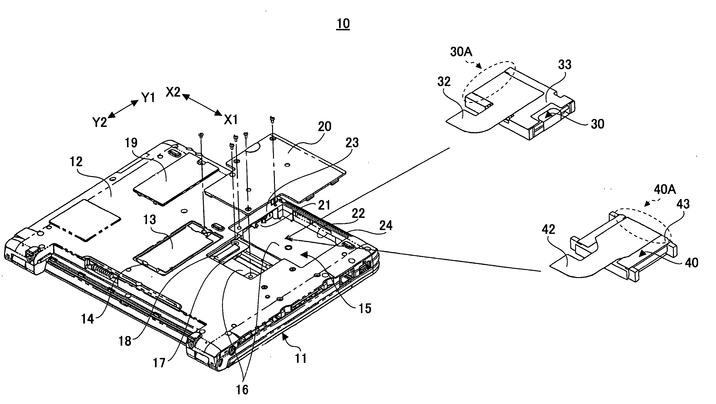
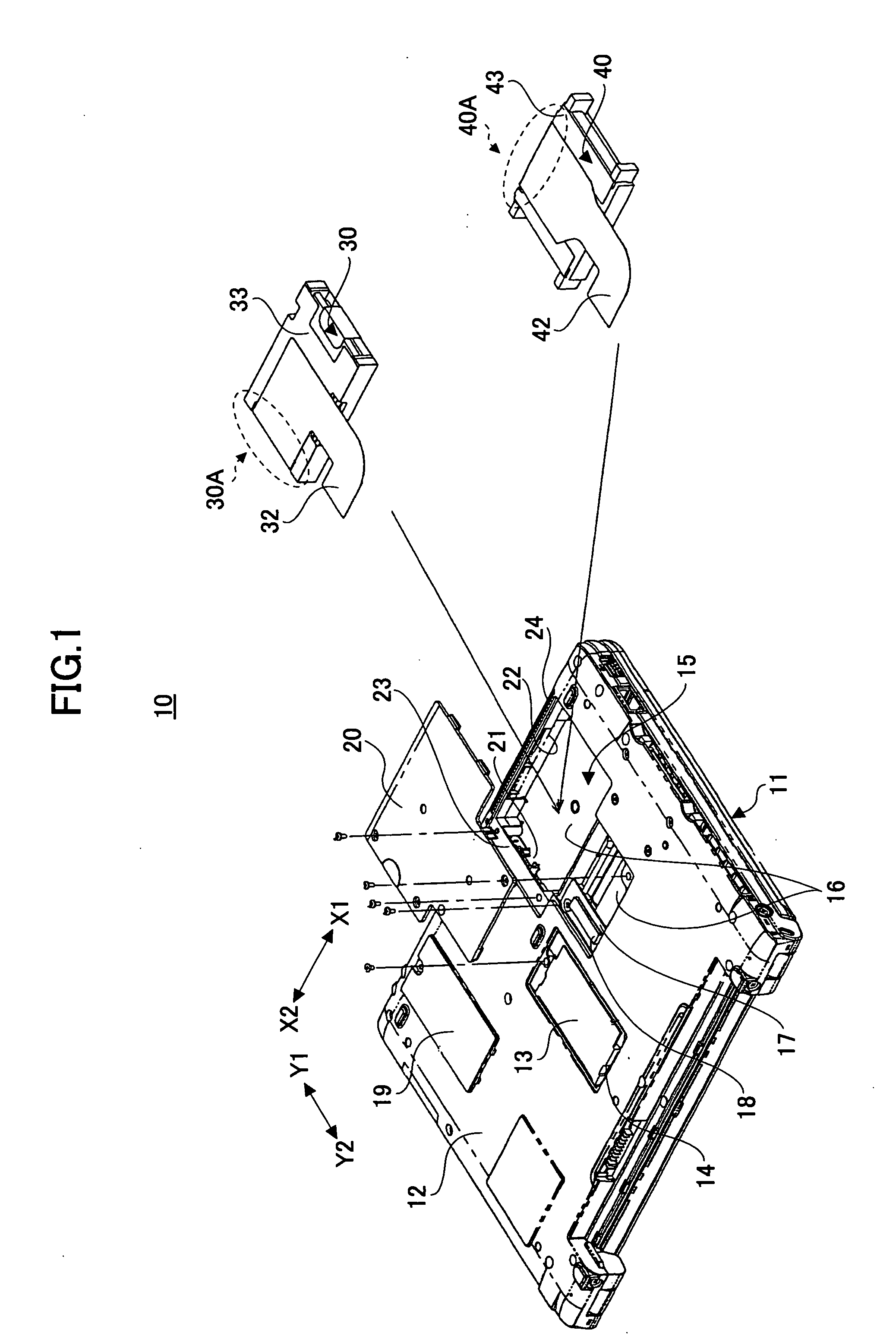
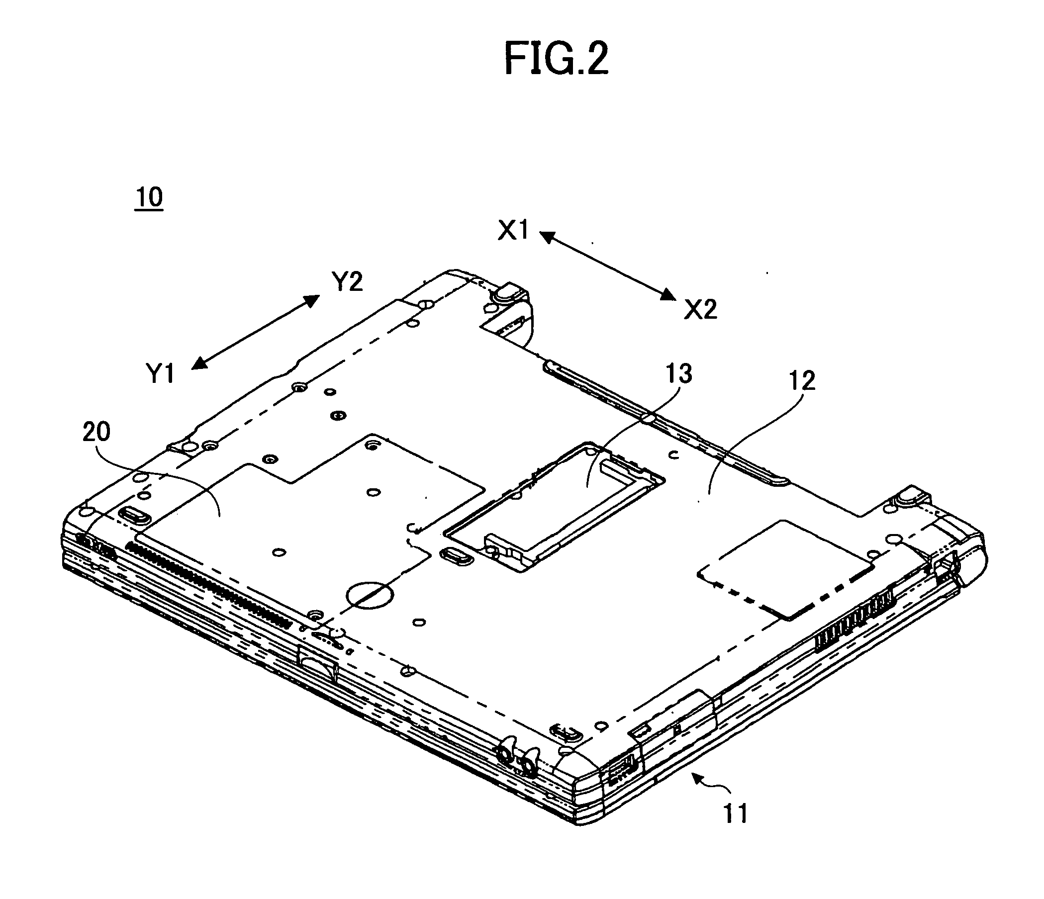
[0055] A description is next given, with reference to FIG. 1 through FIG. 10, of embodiments of the present invention.

[0056]FIG. 1 and FIG. 2 are perspective views showing a bottom surface of a portable electronic device 10 of an embodiment of the present invention. In this embodiment, a portable (lap top type) personal computer is used as the portable electronic device 10. For explanation thereof, an illustration of a cover body part of the portable electronic device 10 where a liquid crystal display device is installed, is omitted in FIG. 1 and FIG. 2.

[0057] The portable electronic device 10 has a housing 11. A keyboard, a flat point, and others are provided at a side of a front surface (not shown in FIG. 1 and FIG. 2) of the housing 11. A module receiving part 14, an HDD receiving part 15, an opening part 16, and others are formed at a bottom surface 12 of the housing 11.

[0058] An expansion module 13 such as an expansion memory is received at the module receiving part 14. The ...


PUM


Abstract

An electronic device includes a housing and a receiving part formed in the housing and configured to receive a received device. A part of the receiving part has a shield structure whereby electromagnetic interference is prevented from radiating.

Description

BACKGROUND OF THE INVENTION [0001] 1. Field of the Invention [0002] The present invention generally relates to electronic devices, and more particularly, to an electronic device having a structure where a received device is provided in a receiving part which is formed in a housing of the electronic device. [0003] 2. Description of the Related Art [0004] In an electronic device such as a personal computer (hereinafter, “PC”), a received device, such as a hard disk drive (hereinafter, “HDD”) as a storage device of the PC, is provided inside of a housing. See Japan Laid-Open Patent Publication No. 11-184562. Furthermore, in a portable electronic device such as a mobile phone, a battery as an electronic power source is provided inside of the housing. See Japan Utility Model Registration Publication No. 07-036479. Therefore, receiving parts (space forming parts) for receiving the HDD or the battery are provided in these electronic devices. [0005] A cover body is provided at a part facing...

Claims


Application Information

Patent Timeline
IPC IPC(8): H05K5/00H05K7/00
CPCG06F1/1656H05K9/0007G11B33/124
Inventor MIZUNO, YUSUKEKOBAYASHI, SONOMASAGOTO, KATSUICHI
Owner FUJITSU LTD
Learn More