Image generation device

a technology of image generation and display device, which is applied in the field of image generation device, can solve the problems of reducing the number of cameras, reducing the resolution of the image displayed on the monitor display, and affecting the viewing of the displayed imag

Inactive Publication Date: 2006-01-26
OLYMPUS CORP
View PDF3 Cites 140 Cited by
  • Summary
  • Abstract
  • Description
  • Claims
  • Application Information

AI Technical Summary

Problems solved by technology

When a wide angle camera is used for this purpose, the number of cameras can be reduced, however, a resolution of the image displayed on a monitor display is lowered and the displayed image becomes difficult to be viewed, so that the observation function is worsened.

Method used


Image

  • Image generation device
  • Image generation device
  • Image generation device

Examples


Embodiment Construction

[0034] Hereinafter, embodiments for the image generation device according to the present invention will be explained in detail by referring to the accompanying drawings.

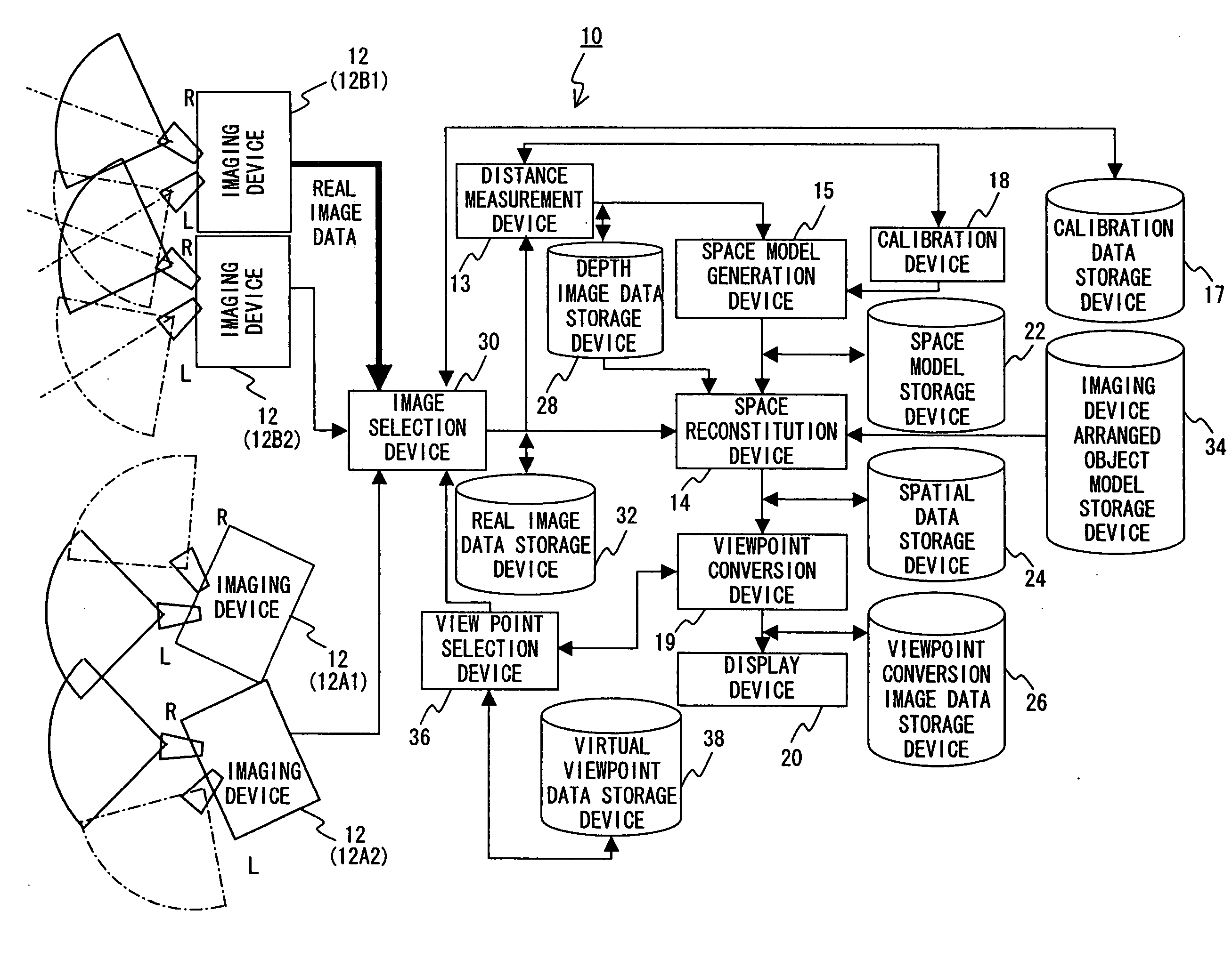
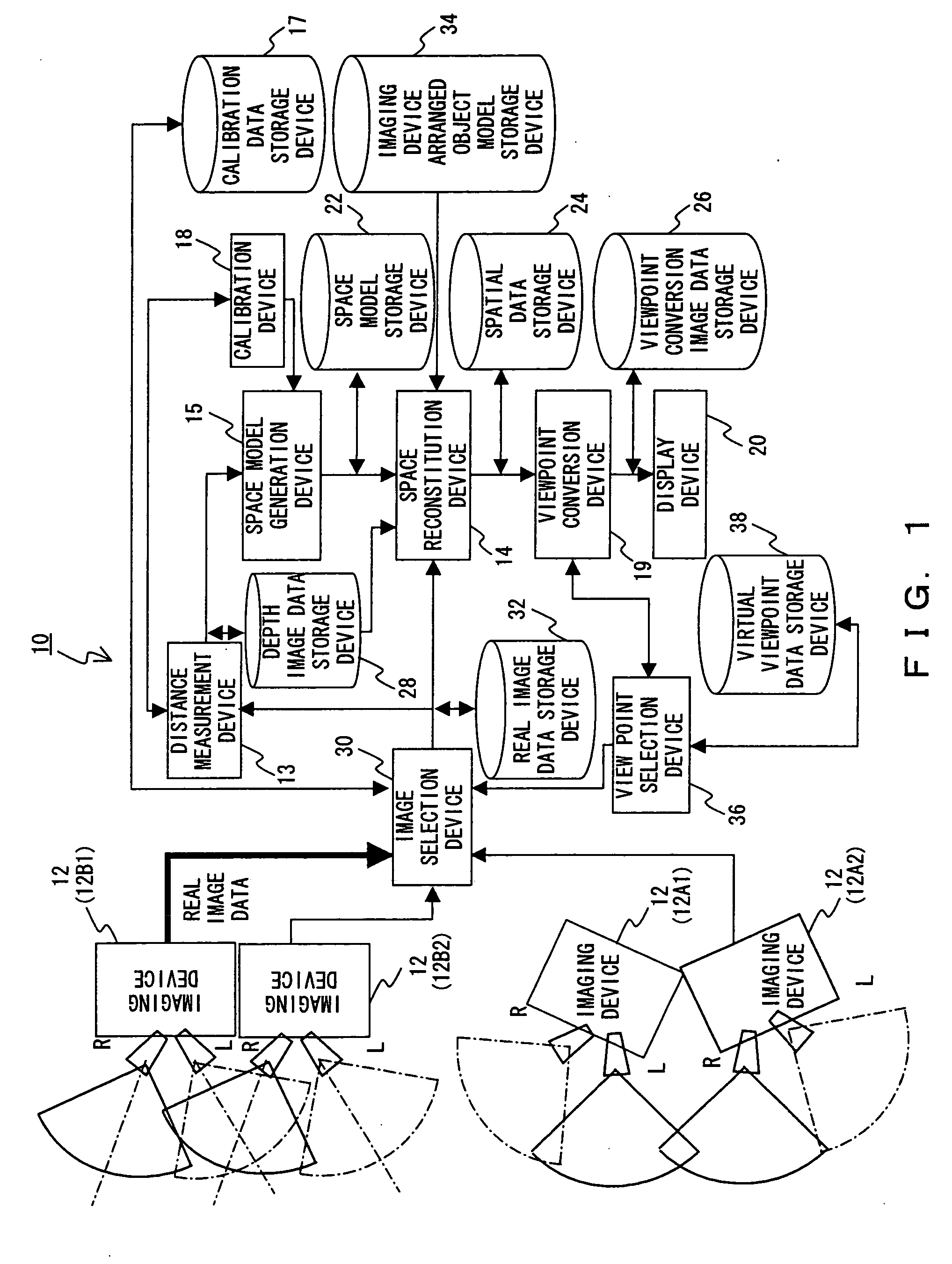
[0035]FIG. 1 is a system block diagram showing a configuration of an image generation device for implementing the present invention. The basic configuration of this system is provided with a viewpoint conversion synthesized image generation / display device 10 comprising a plurality of imaging units, an image generation device for processing image data acquired by the imaging units and reproducing and displaying the image as a synthesized image viewed from a virtual viewpoint which is different from the viewpoint of the camera.

[0036] Basically, the viewpoint conversion synthesized image generation / display device 10 executes a process of inputting images imaged from viewpoints of respective imaging units, a process of setting a three-dimensional space in which a imaging unit arranged object such as a vehicle is placed...


PUM


Abstract

In a device for generating one viewpoint conversion image based on a plurality of image data, a first unit including two cameras with different viewpoints, for acquiring one of the image data, and a second unit, including two cameras with different viewpoints, which is arranged in line with the first unit so that the first and second units are in a positional relationship where the optical axis direction of a imaging lens of at least one of the two cameras included in the second unit is parallel to the optical axis direction of a imaging lens of one of the cameras included in the first unit, for acquiring the other one of the image data are provided. The units are arranged so that the imaging lenses of the two cameras included in the first and the second units have optical axes which are not parallel to each other.

Description

CROSS REFERENCE TO RELATED APPLICATIONS [0001] This application claims benefit of Japanese Application No. 2004-211371, filed Jul. 20, 2004, the contents of which are incorporated by this reference. BACKGROUND OF THE INVENTION [0002] 1. Field of the Invention [0003] The present invention relates to an image generation device, and particularly to an image generation device suitable for generating and displaying a viewpoint conversion image based on a plurality of images. [0004] 2. Description of the Related Art [0005] When images are displayed on a monitor display for purposes of an observation of a particular area or the like, images acquired by imaging a wide range of areas by a plurality of cameras are displayed on a divided screen, or such images are displayed by being sequentially switched as time elapses. Also, for a safe drive, a camera facing backward is provided on a vehicle for imaging an area which a driver can not directly or indirectly view so that the image of the area ...

Claims


Application Information

Patent Timeline
Patent Type & Authority Applications(United States)
IPC IPC(8): G06K9/00H04N13/239H04N13/243
CPCG06T5/006G06T7/002G06T7/0075H04N13/0242H04N13/0014H04N13/0239G06T2207/10012G06T7/85G06T7/593H04N13/243H04N13/117H04N13/239
Inventor MIYOSHI, TAKASHIIWAKI, HIDEKAZUKOSAKA, AKIO
Owner OLYMPUS CORP
Why Eureka
Try Eureka