Connector unit for differential transmission

a technology for connecting units and differential transmissions, applied in the direction of coupling contact members, coupling device connections, connection contact member materials, etc., can solve the problems of easy rubbing of gold plating layer on fracture surfaces compared with that on rolled surfaces, complicated structure of differential transmission connectors, and considerable rough fracture surfaces due to press work

Inactive Publication Date: 2006-01-26
FUJITSU COMPONENENT LTD
View PDF3 Cites 65 Cited by
  • Summary
  • Abstract
  • Description
  • Claims
  • Application Information

AI Technical Summary

Benefits of technology

[0029] Accordingly, it is a general object of the present invention to provide a diffe...

Problems solved by technology

Compared with normal connectors, the differential transmission connector has a complicated structure.
Here, the fracture surfaces due to press working were found to be ...

Method used


Image

  • Connector unit for differential transmission
  • Connector unit for differential transmission
  • Connector unit for differential transmission

Examples


first embodiment

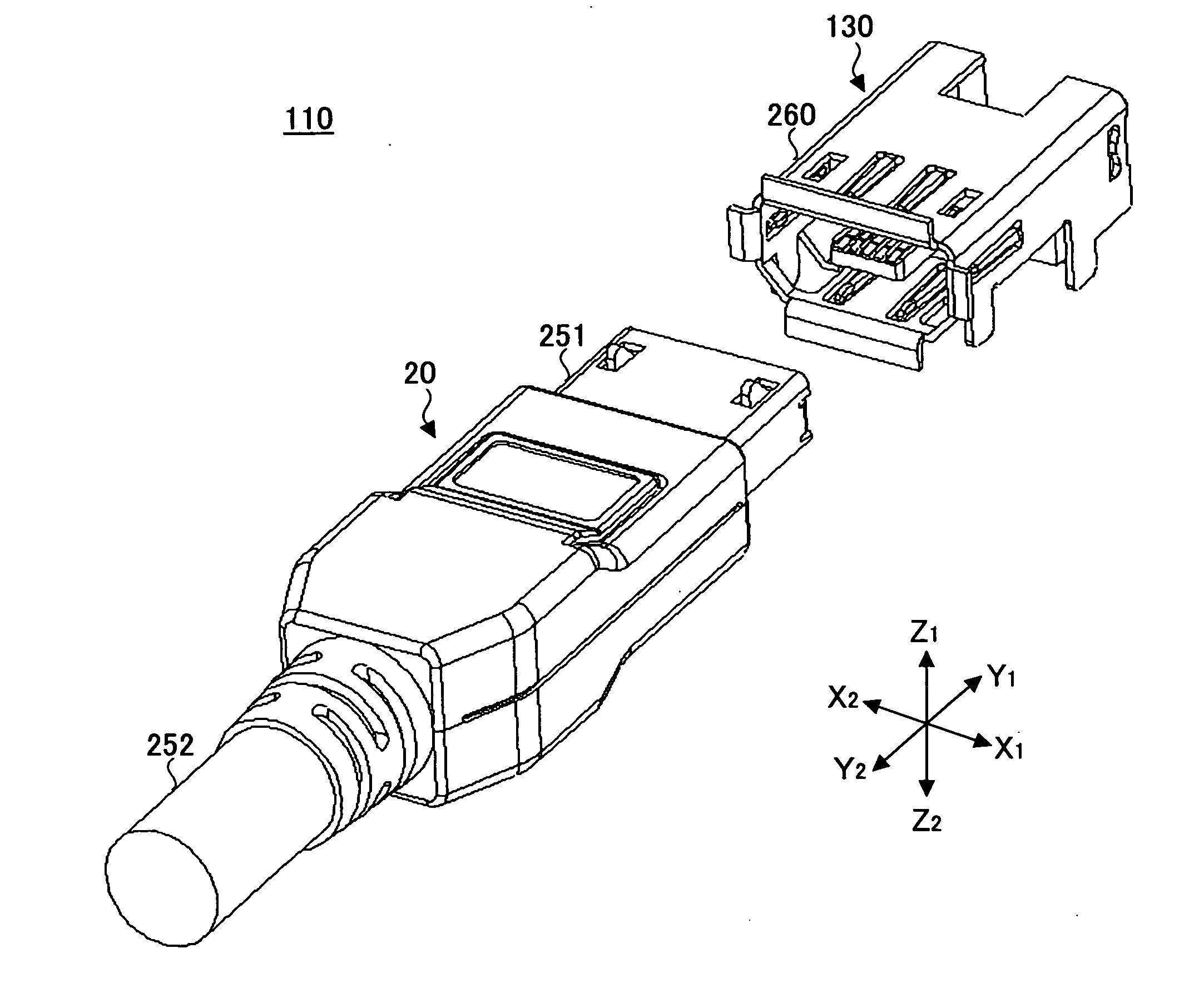
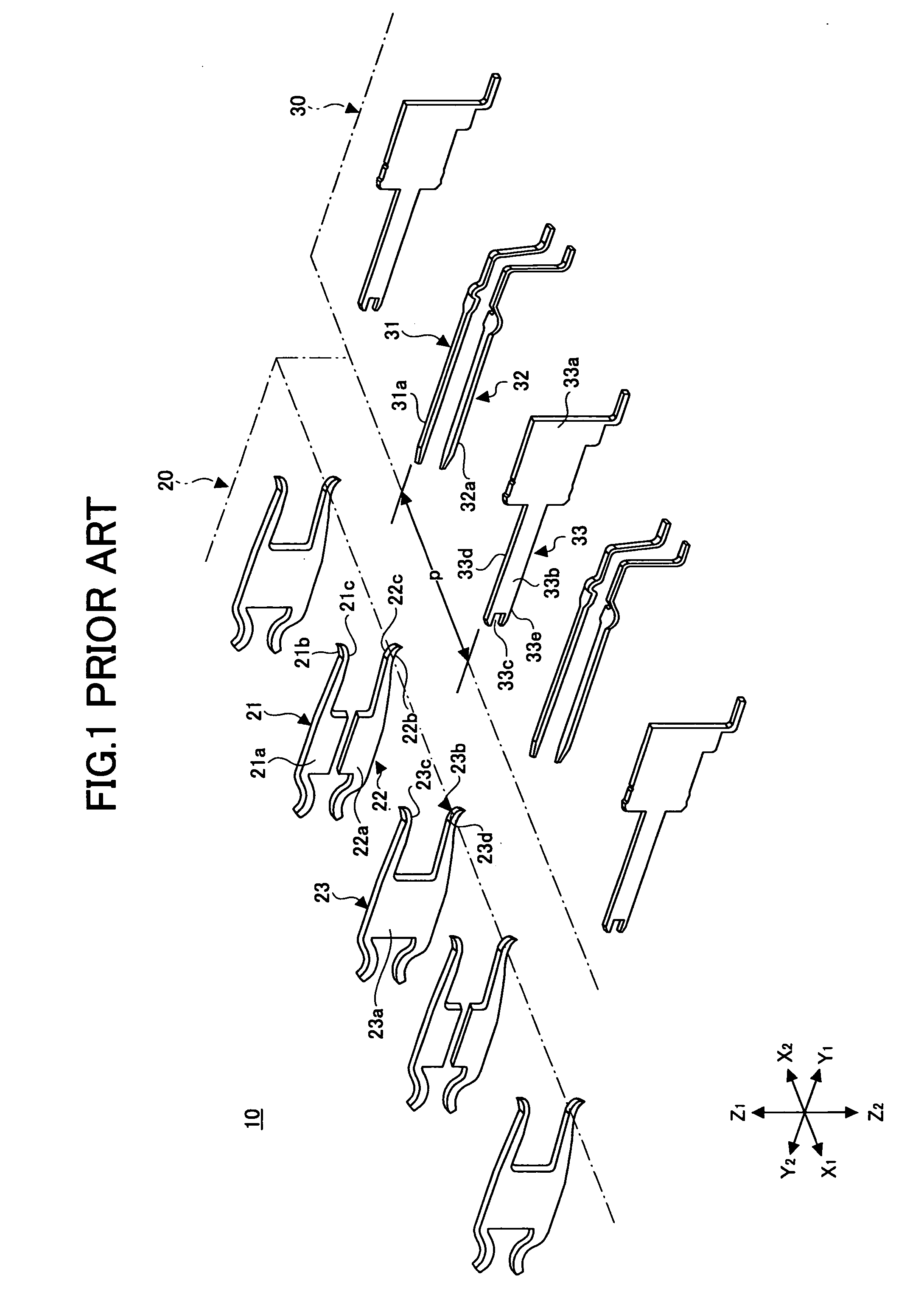
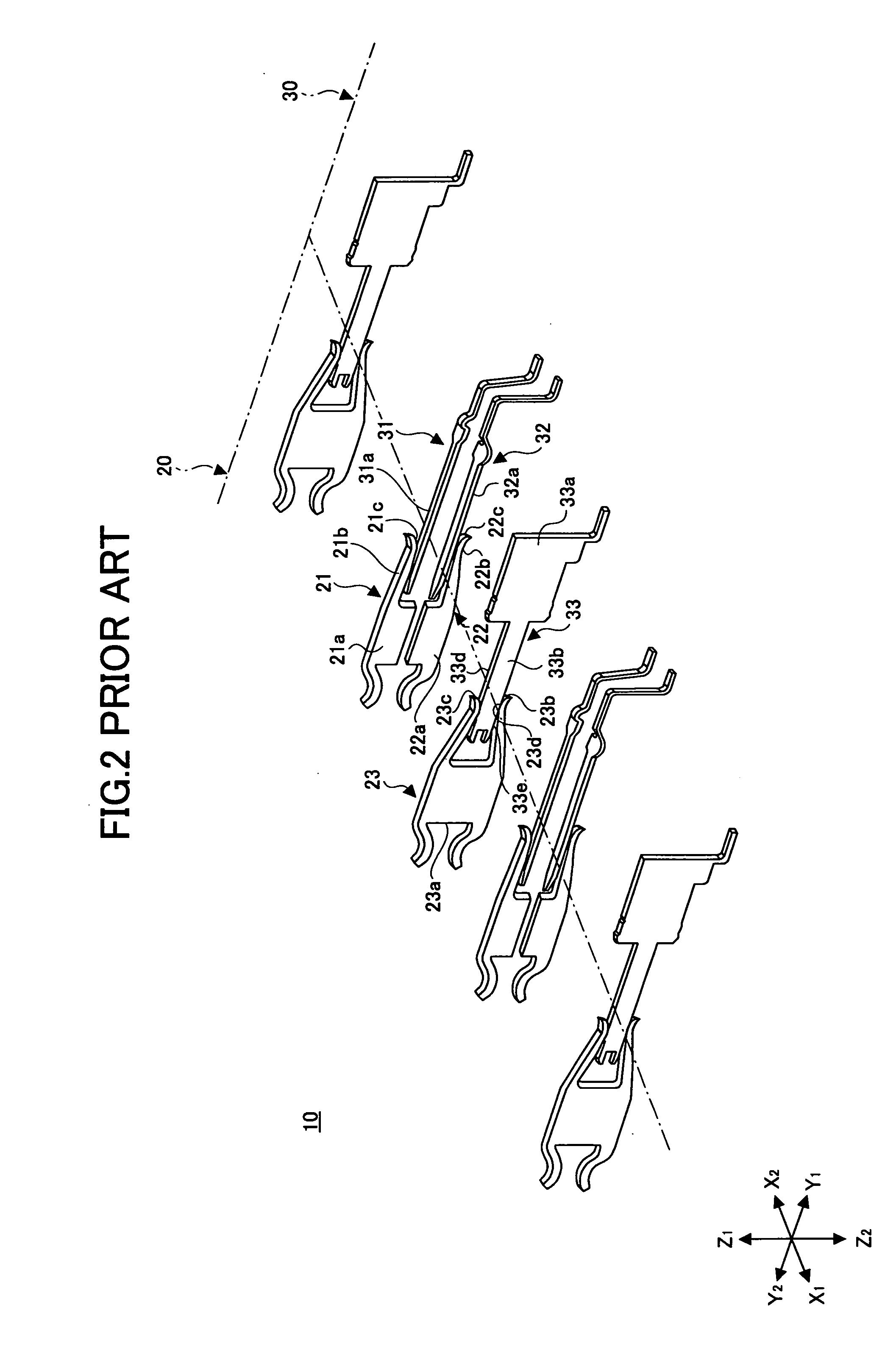
[0068]FIGS. 9 and 10 are diagrams illustrating a connector unit for differential transmission (differential transmission connector unit) 110 according to a first embodiment of the present invention. The differential transmission connector unit 110 includes a socket connector 130 to be mounted on a printed board and the cable connector 20 at a cable end. The socket connector 130 is different in configuration from the socket connector 30 of the differential transmission connector unit 10 illustrated in FIG. 1.

[0069]FIG. 9 illustrates a state where the cable connector 20 and the socket connector 130 oppose each other. FIGS. 10 through 14 are diagrams each illustrating a state where the cable connector 20 is inserted in the socket connector 130 to be connected thereto. FIG. 10 is a bottom perspective view of the differential transmission connector unit 110. FIG. 11 is a longitudinal sectional view of the differential transmission connector unit 110 of FIG. 10 taken along the plane XI, ...

second embodiment

[0098]FIG. 25A is a perspective view of a differential transmission connector unit 110C according to a second embodiment of the present invention. The differential transmission connector unit 110C includes a cable connector 20C and a socket connector 130C. FIG. 25A illustrates a state where the cable connector 20C is-inserted halfway into the socket connector 130C. FIG. 25B illustrates the Y2 end part of an electrically insulating block body 140C of the socket connector 130C. FIG. 26A is a schematic diagram illustrating a state where a signal contact pair formed of the first and second signal contacts 21 and 22 and a ground contact 23C of the cable connector 20C oppose a corresponding signal contact pair formed of the first and second signal contacts 31 and 32 and a corresponding ground contact 133C, respectively, of the socket connector 130C. FIG. 26B is a schematic diagram illustrating a state where the cable connector 20C is inserted in and connected to the socket connector 130C ...

third embodiment

[0110]FIG. 30 is a schematic diagram illustrating a differential transmission connector unit 110D according to a third embodiment of the present invention. The differential transmission connector unit 110D includes a cable connector 20D and a socket connector 130D. FIG. 31A illustrates a state where one of ground contacts 23D incorporated in the cable connector 20D opposes a corresponding one of ground contacts 133D incorporated in the socket connector 130D. The ground contacts 23C and 133C are partially modified into the ground contacts 23D and 133D, respectively.

[0111] As illustrated in FIG. 31A, the ground contact 23D includes a plate part 23Da, a bent part 23Dd, and an extension plate part 23De. Unlike the extension plate part 23Ce of the ground contact 23C of the second embodiment, the extension plate part 23De is not forked. The ground contact 23D includes a contact part 23Dh at the Y1 end of the extension plate part 23De, and a contact surface 23Di on the X2 side of the cont...


PUM


Abstract

A differential transmission connector unit is disclosed that includes a first differential transmission connector including a first electrically insulating block body; and first signal contact pairs and first ground contacts arranged alternately in a row in the first block body; and a second differential transmission connector including a second electrically insulating block body; and second signal contact pairs and second ground contacts arranged alternately in a row in the second block body. The first differential transmission connector is connected to the second differential transmission connector with the first signal contact pairs and the second signal contact pairs being in contact with each other and the first ground contacts and the second ground contacts being in contact with each other. One of the contact surface of each first ground contact and the contact surface of the corresponding second ground contact is a rolled surface, the contact surfaces contacting each other.

Description

BACKGROUND OF THE INVENTION [0001] 1. Field of the Invention [0002] The present invention relates to a connector unit for differential transmission. [0003] 2. Description of the Related Art [0004] There are two types of data transmission methods: a normal transmission method and a differential transmission method. The normal transmission method employs an electric wire for each data item. The differential transmission method, using a pair of electric wires for each data item, simultaneously transmits a “+” signal to be transmitted and a “−” signal equal in magnitude and opposite in direction to the “+” signal. The differential transmission method, which has the advantage of being less susceptible to noise compared with the normal transmission method, has been used more widely. [0005] A connector is used to transmit data between apparatuses. In order to form a data path for differential transmission between the apparatuses, a connector for differential transmission (a differential tr...

Claims


Application Information

Patent Timeline
IPC IPC(8): H01R24/00
CPCH01R13/26H01R13/6585H01R13/6471H01R13/65807
Inventor MORIYAMA, SATOSHIKUMAMOTO, TADASHIHAMAZAKI, MASAHIROKOBAYASHI, MITSURUSATO, KIYOSHI
Owner FUJITSU COMPONENENT LTD
Why Eureka
Try Eureka