Small form factor air jet cooling system

a cooling system and small form factor technology, applied in the direction of cooling/ventilation/heating modifications, electrical apparatus casings/cabinets/drawers, electrical apparatus, etc., can solve the problems of limiting the available fan size and space, complicated management of these increased heat-dissipation requirements, etc., and achieve the effect of adding cooling efficiency

Active Publication Date: 2006-01-26
HEWLETT-PACKARD ENTERPRISE DEV LP
View PDF50 Cites 21 Cited by
  • Summary
  • Abstract
  • Description
  • Claims
  • Application Information

AI Technical Summary

Benefits of technology

[0007] The invention features a cooling system including a plenum and a blower, the blower being configured to pressurize the plenum. The plenum defines a plurality of orifices in the chassis, each orifice being configured to direct pressu

Problems solved by technology

Managing these increased heat-dissipation requirements is complicated by the limited size of the 1U chassis.
In particular, the small form factor limits both the available fan sizes and the space for air to flow through the chassis.
The limited space typically includes many impediments, such as heat sinks, wires and components, causing sign

Method used


Image

  • Small form factor air jet cooling system
  • Small form factor air jet cooling system
  • Small form factor air jet cooling system

Examples


Embodiment Construction

[0018] The invention summarized above and defined by the enumerated claims may be better understood by referring to the following detailed description, which should be read with the accompanying drawings. This detailed description of particular preferred embodiments of the invention, set out below to enable one to build and use particular implementations of the invention, is not intended to limit the enumerated claims, but rather, it is intended to provide particular examples of them.

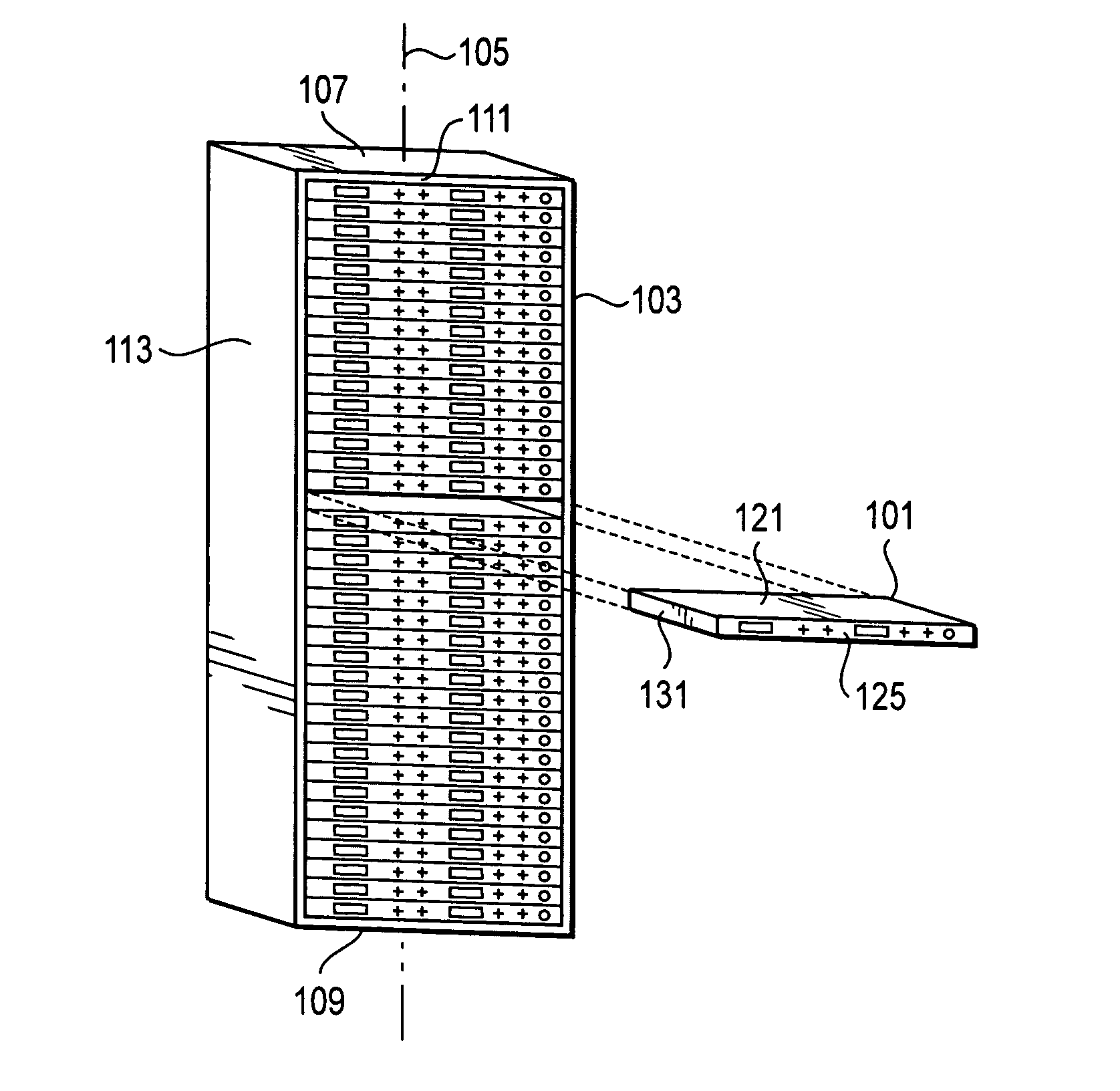
[0019] Typical embodiments of the present invention reside in a computer processing system including a tiered apparatus for supporting, cooling, and connecting or interconnecting a plurality of thin, stackable computer chassis. The tiered apparatus is typically in the form of a multi-tiered modular support rack, which can optionally be configured with wiring such that the computer chassis receive power, and interconnect to form networked computer systems or other electronic devices. One or more of the ...


PUM


Abstract

An enclosure forms a plurality of tiers vertically stacked in a longitudinal dimension. Each tier is a 1U modular computer system having a computer chassis configured for mounting in the multi-tiered support, and computer components that need cooling within the computer chassis. A cooling system is formed by a plenum pressurized by a blower. The plenum defines a plurality of configurable orifices in the chassis, each directing pressurized air toward a component. The plenum includes adjustable valves to controllably limit airflow through the orifices, and a controller to control the air pressure within the plenum and the orifice flow rates through the valves.

Description

[0001] The present invention relates generally to multi-tiered, modular rack systems for components and, more particularly, to a cooling system for cooling components in a small form factor chassis mounted in a standardized system rack. BACKGROUND OF THE INVENTION [0002] Multi-tiered, modular racks are commonly used with groups of modular chassis. Such racks commonly provide each chassis access to network connections and electrical power. A typical chassis might contain components and interconnecting devices (e.g., printed circuit board cards and wires) that form a computer system such as a server. Each chassis functions to provide an environment relatively free from excessive heat, shock, vibration and / or dust for the computer system. Groups of these computer systems are interconnected to form electronic applications, such as server farms that serve the networking needs of business organizations. [0003] In present-day, standardized racks, 1U “pizza-box” chassis (being 1.75 inches t...

Claims


Application Information

Patent Timeline
IPC IPC(8): H05K5/00
CPCH05K7/20727
Inventor BEITELMAL, ABDLMONEM H.PATEL, CHANDRAKANT D.BASH, CULLEN E.
Owner HEWLETT-PACKARD ENTERPRISE DEV LP
Why Eureka
Try Eureka