Power control for a wireless communication system utilizing orthogonal multiplexing

a wireless communication system and power control technology, applied in the field of communication, can solve the problems of inability to achieve complete orthogonality between the transmissions of different terminals, interference to terminals communicating with nearby base stations, and large amounts of interference, so as to achieve the effect of reducing the transmission power

Active Publication Date: 2006-01-26
QUALCOMM INC
View PDF99 Cites 347 Cited by
  • Summary
  • Abstract
  • Description
  • Claims
  • Application Information

AI Technical Summary

Benefits of technology

[0011] In general, the transmit power may be decreased if high interference is observed by neighbor base stations and increased if low interference is observed. The transmit power may also be adjusted by a larger amount and / or more frequently if (1) the terminal is located closer to a neighbor base station observing high interference and / or (2) the current transmit power level is higher. The transmit power may be adjusted by a smaller amount and / or less frequently if (1) the terminal is located closer to the serving base station and / or (2) the current transmit power level is lower. The intra-sector interference caused by the terminal is maintained within an acceptable level by limiting the received signal quality (SNR) for the data transmission to be within a range of allowable SNRs.

Problems solved by technology

However, complete orthogonality among the transmissions from different terminals is often not realized due to channel conditions, receiver imperfections, and so on.
The loss in orthogonality results in each terminal causing some amounts of interference to other terminals communicating with the same base station.
Thus, each terminal may also cause interference to terminals communicating with nearby base stations.
The performance of each terminal is then degraded by the interference from all other terminals in the system.

Method used


Image

  • Power control for a wireless communication system utilizing orthogonal multiplexing
  • Power control for a wireless communication system utilizing orthogonal multiplexing
  • Power control for a wireless communication system utilizing orthogonal multiplexing

Examples


Embodiment Construction

[0021] The word “exemplary” is used herein to mean “serving as an example, instance, or illustration.” Any embodiment or design described herein as “exemplary” is not necessarily to be construed as preferred or advantageous over other embodiments or designs.

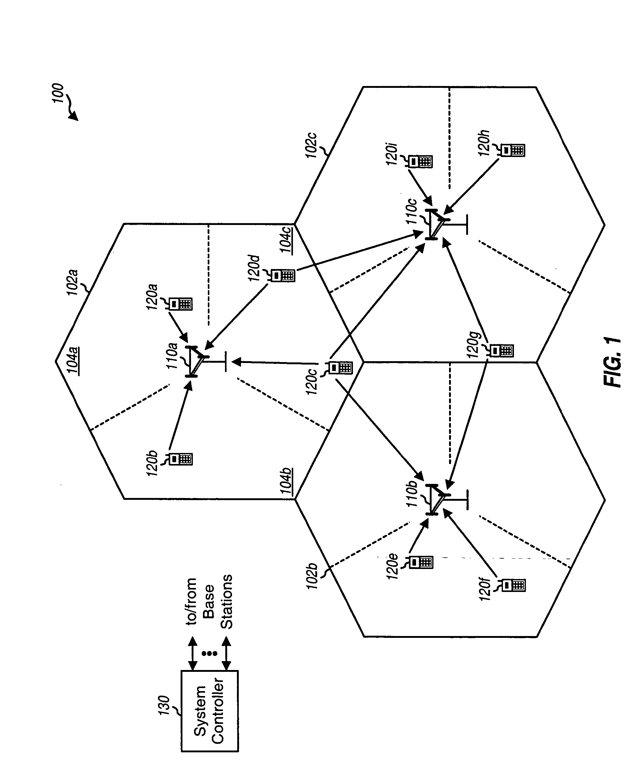
[0022]FIG. 1 shows a wireless multiple-access communication system 100. System 100 includes a number of base stations 110 that support communication for a number of wireless terminals 120. Terminals 120 are typically dispersed throughout the system, and each terminal may be fixed or mobile. A terminal may also be referred to as a mobile station, a user equipment (UE), a wireless communication device, or some other terminology. A base station is a fixed station used for communicating with the terminals and may also be referred to as an access point, a Node B, or some other terminology. A system controller 130 couples to base stations 110, provides coordination and control for these base stations, and further controls the routing ...


PUM


Abstract

Techniques for adjusting transmit power to mitigate both intra-sector interference to a serving base station and inter-sector interference to neighbor base stations are described. The amount of inter-sector interference that a terminal may cause may be roughly estimated based on the total interference observed by each neighbor base station, channel gains for the serving and neighbor base stations, and the current transmit power level. The transmit power may be decreased if high interference is observed by a neighbor base station and increased otherwise. The transmit power may be adjusted by a larger amount and / or more frequently if the terminal is located closer to the neighbor base station observing high interference and / or if the current transmit power level is higher, and vice versa. The intra-sector interference is maintained within an acceptable level by limiting a received SNR for the terminal to be within a range of allowable SNRs.

Description

CLAIM OF PRIORITY UNDER 35 U.S.C. §119 [0001] The present Application for Patent claims priority to Provisional Application No. 60 / 580,819 entitled “Reverse-Link Power Control Algorithm” filed Jun. 18, 2004, and assigned to the assignee hereof and hereby expressly incorporated by reference herein.REFERENCE TO CO-PENDING APPLICATIONS FOR PATENT [0002] The present application for patent is related to the following co-pending U.S. patent applications: [0003]“Robust Erasure Detection and Erasure-Rate-Based Closed Loop Power Control” by Arak Sutivong et al, having Attorney Docket No. 040404U1, filed Jul. 13, 2004, assigned to the assignee hereof, and expressly incorporated by reference herein. BACKGROUND [0004] I. Field [0005] The present invention relates generally to communication, and more specifically to power control for a wireless communication system. [0006] II. Background [0007] A wireless multiple-access communication system can simultaneously support communication for multiple ...

Claims


Application Information

Patent Timeline
Patent Type & Authority Applications(United States)
IPC IPC(8): H04Q7/20H04B7/005H04L1/00H04L1/20H04W24/00H04W28/04H04W52/24H04W52/28H04W52/36H04W52/60H04W88/08
CPCH04W24/00H04W28/04H04W52/24H04W52/241H04W52/242H04W88/08H04W52/283H04W52/36H04W52/362H04W52/367H04W52/60H04W52/243H04L1/0045H04L1/0057H04L1/20H04W52/125H04W52/50H04W52/146H04W52/16H04W52/20H04W52/247H04W52/54H04B17/309H04W52/18
Inventor SUTIVONG, ARAKAGRAWAL, AWNEESHJULIAN, DAVID JONATHAN
Owner QUALCOMM INC
Why Eureka
Try Eureka