
Fatigue-resistance sheet slitting method and resulting sheet

Inactive Publication Date: 2006-02-02
IND ORIGAMI INC CA US
View PDF53 Cites 31 Cited by
  • Summary
  • Abstract
  • Description
  • Claims
  • Application Information

AI Technical Summary

Benefits of technology

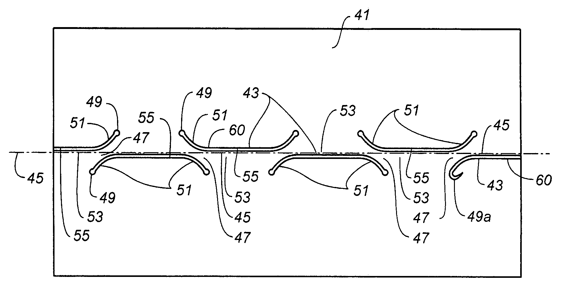
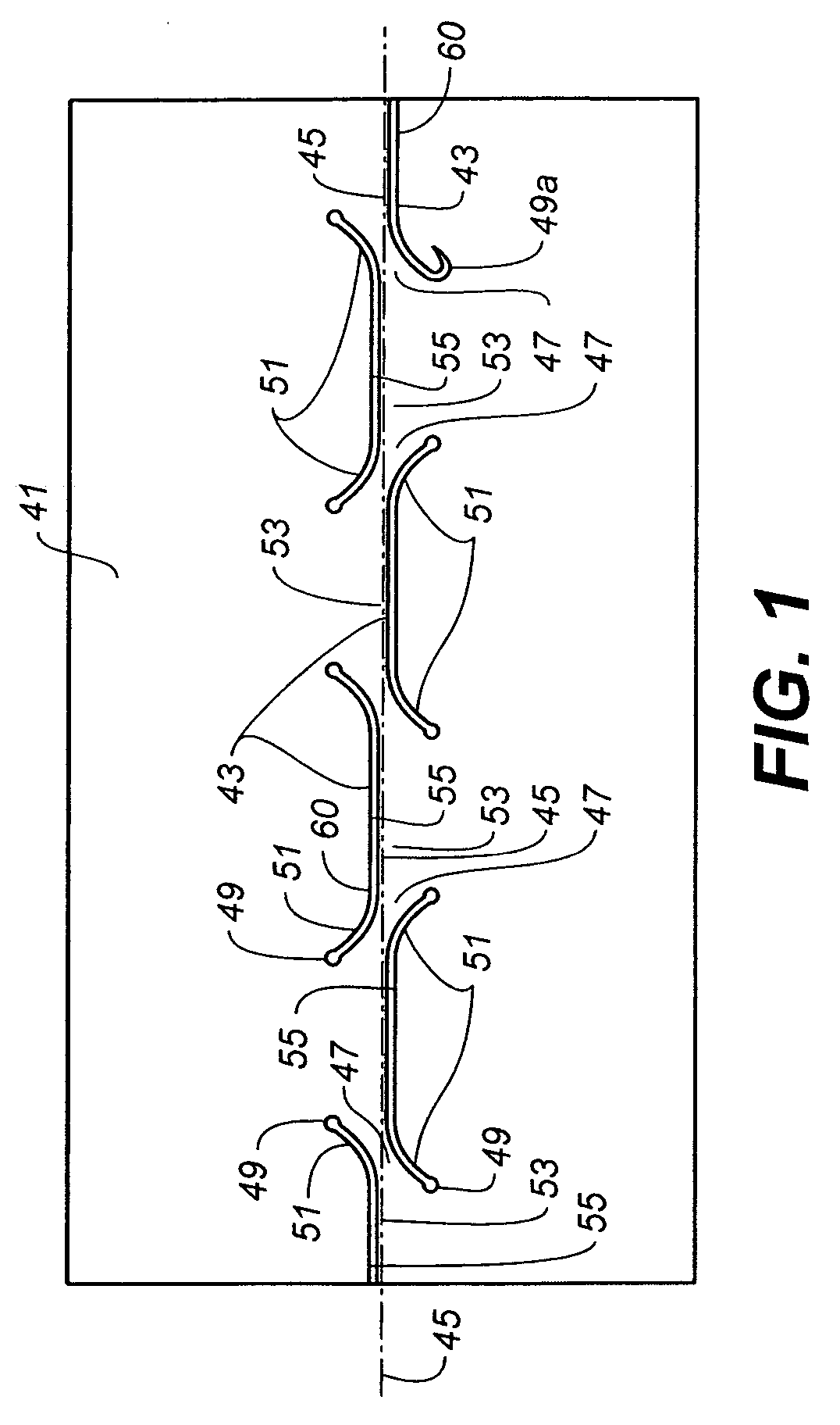
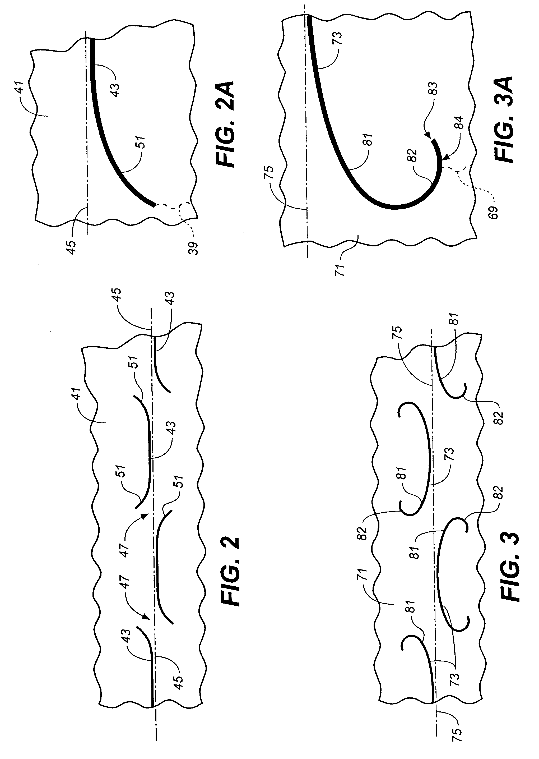
[0022] In one aspect, the present invention is comprised of a sheet of material formed for bending along a bend line and having a plurality of bend-inducing structures configured and positioned to produce bending along the bend line. At least one of the bend-inducing structures, and preferably all of them, have arcuate return portions extending from opposite ends of the bend-inducing structure and returning along the bend-inducing structure toward the other return portion. The return portions each are configured to significantly increase resistance to fatigue resulting from cyclical loads oriented in a direction transverse to the bend line by having arcuate lengths and radii reducing stress concentrations. The bend-inducing structures preferably are slits, grooves or steps which are configured to produce edge-to-face engagement on opposite sides of the bend-inducing structures during bending. Stress concentrations can be reduced by forming the arcuate return portions with a cord length at least approximately twice the thickness dimension of the sheet of material. The arcuate return portions further preferably have chords oriented substantially parallel to the bend line, and a radii of curvature of the return portions which are at least approximately three times the thickness dimension of the sheet of material.
[0023] In another aspect of the present invention a method of increasing the fatigue resistance of a structure formed by bending a sheet of material along a bend line having a plurality of bend-inducing structures is provided. The method comprises, briefly, the step of forming the bend-inducing structures to extend along the bend line and have arcuate return portions extending from opposite ends of the bend-inducing structures back along the bend-inducing structures toward the other return portion. The return portions have a length dimension along the bend line and a radius of curvature selected to be sufficiently large to significantly increase resistance to fatigue upon cyclical loading of the structures transverse to the bend line.

Problems solved by technology

A commonly encountered problem in connection with bending sheet material using conventional sheet bending equipment, such as a press brake, is that the locations of the bends are difficult to control because of bending tolerance variations and the accumulation of tolerance errors.
A second bend, however, often is located based upon the first bend, and accordingly, the tolerance errors can accumulate.
Since there can be three or more bends which are involved to create an enclosure or closed structure, the effect of cumulative tolerance errors in conventional prior art bending techniques can be significant.
In most of these prior art sheet bending systems, however, the bend-inducing structures greatly weaken the resulting structure, or the bend-inducing structures do not produce the desired precision in the location of the bends, or both.
The problems of precision bending and retention of strength are much more substantial when bending metal sheets, and particularly metal sheets of substantial thickness.
In the case of welding, problems arise in the accurate cutting and positioning of the individual pieces during welding, and the labor required to manipulate a large number of parts is significant, as are the quality control and certification burden.
Additionally, welding has potential problems in connection with dimensional stability caused by the heat affected zone of the weld.
This adds significantly to the fabrication time and cost.
Moreover, fatigue failure of heat affected metals under cyclical loading is a problem for joints whose load bearing geometries are based upon welding, brazing or soldering.
Press brake bending, by contrast, is not well suited to form closed structures such as box beams.
Such loading is often cyclical and results in fatiguing of the beam at its corners.
For welded box beams, therefore, fatigue failure typically occurs along the welded corners, and if a bent sheet is to be used, the corner bend lines will also be the area most likely to fail.

Method used


Image

  • Fatigue-resistance sheet slitting method and resulting sheet
  • Fatigue-resistance sheet slitting method and resulting sheet
  • Fatigue-resistance sheet slitting method and resulting sheet

Examples


examples

[0060]FIG. 6 schematically illustrates a box beam as positioned on a fatigue test stand. The box beams tested each had a square cross-section with a dimension of 4 inches on each side and included a flange 132 which was folded inside one of the sidewalls and secured thereto by fastener assemblies 133, in this case a bolt and nut. The fasteners were placed every 4 inches along the length of the beam, and beam 131 had an overall length of 48 inches. A support assembly 135 was provided proximate each end of beam 131, and forced distributing plates 137 used to avoid local concentrations of stress at support stands 135.

[0061] Beam 131 was loaded at two locations 139 on either side of the center of the beam. The loads were spaced from each other by a distance of approximately 6 inches. Again, load distributing plates were employed at 139, and arrows 141 schematically illustrate that the beam was loaded from a minimum load up to a maximum load. Loading was cycled between minimum and maxim...


PUM

PropertyMeasurementUnit
Fractionaaaaaaaaaa
Lengthaaaaaaaaaa
Thicknessaaaaaaaaaa

Abstract

A sheet of material (111) having a plurality of bend-inducing structures (113) configured and positioned to produce bending along a bend line (115). The bend-inducing structures (113) have arcuate return portions (122) extending from opposite ends (121) back along the bend-inducing structures (113) toward the other return portion (122) and each return portion (122) has a length dimension and a radius of curvature reducing stress concentrations. Preferably, the length dimension of the arcuate return portion (122) is in excess of twice the thickness. The lateral distance, LD, to which the bend-inducing structures (113) is formed in the sheet away from the bend line (115) is preferably minimized by small radius arcs (125) which connect the return portions (122) to the remainder of the bend-inducing structures (113). A method of forming a structure (131) from a sheet of material (111) to resist cyclical loading is also disclosed, as is a method to increase the fatigue resistance of a structure (131) formed by bending a sheet of material (111) along a bend line (115) having a plurality of bend-inducing structures (113).

Description

CROSS-REFERENCES TO RELATED APPLICATIONS [0001] This application claims priority to U.S. Provisional Patent Application No. 60 / 587,470, filed Jul. 12, 2004, entitled METHOD FOR INCREASING THE FATIGUE RESISTANCE OF STRUCTURES FORMED BY BENDING SLIT SHEET MATERIAL AND PRODUCTS RESULTING THEREFROM, the entire contents of which is incorporated herein by this reference. [0002] This application is also a Continuation-in-Part Application of U.S. patent application Ser. No. 10 / 672,766, filed Sep. 26, 2003, and entitled TECHNIQUES FOR DESIGNING AND MANUFACTURING PRECISION-FOLDED, HIGH STRENGTH, FATIGUE-RESISTANT STRUCTURES AND SHEET THEREFOR, which is a Continuation-in-Part Application of U.S. patent application Ser. No. 10 / 256,870, filed Sep. 26, 2002, and entitled METHOD FOR PRECISION BENDING OF SHEET OF MATERIALS, SLIT SHEETS FABRICATION PROCESS, now U.S. Pat. No. 6,877,349, which is a Continuation-in-Part Application of U.S. patent application Ser. No. 09 / 640,267, filed Aug. 17, 2000, an...

Claims


Application Information

Patent Timeline
IPC IPC(8): B21D5/00
CPCB21D5/00B21D11/20Y10T428/12354B29C53/06B31F1/0012B21D31/00Y10T83/0341B21D28/26
Inventor DURNEY, MAX W.PENDLEY, ALAN D.KOCH, JUSTIN
Owner IND ORIGAMI INC CA US
Learn More