Integral pressure regulation system for tires and other vessels containing compressible fluids

a technology of compression fluid and pressure regulation system, which is applied in the direction of tire measurement, vehicle components, transportation and packaging, etc., can solve the problem of driving on an under-inflated tire that requires extra energy, and achieves the effect of reducing manufacturing costs and support costs, improving vehicle safety, and simplifying maintenan

Active Publication Date: 2006-02-02
BUNKER GRANT
View PDF20 Cites 20 Cited by
  • Summary
  • Abstract
  • Description
  • Claims
  • Application Information

AI Technical Summary

Benefits of technology

[0008] According to the present invention a pressure regulation system for pneumatic tires can have within the tire an outer, or main, chamber containing a volume of compressible fluid such as air, the fluid being maintained at a desired pressure by an inner, or pump, chamber which acts to inflate the main chamber. The pump chamber can include a rigid, fluid-tight wall facing the fluid volume of the main chamber and a flexible wall which can be part of the vessel itself, such as an outer wall or tread wall of the tire, that is deformed under use. The pressure regulation system can further include a fluid channel extending between the pump chamber and an exterior of the tire, with the fluid channel admitting ambient air into the pump chamber. Valving for the pressure regulation and inflation system may include a first valve positioned between the pump chamber and the outer chamber, the first valve being a check valve permitting the ambient fluid to pass from the exterior of the tire into the pump chamber while it is uncompressed, and preventing fluid flow in the reverse direction. A second valve can be positioned between the pump chamber and the main chamber of the tire, with the second valve being a check valve permitting fluid to pass from the pump chamber while it is compressed, to the main chamber, and preventing fluid flow in the reverse direction. A pressure control system, such as a relief valve or other controllable setpoint valves operably positioned with respect to at least one of the pump chamber and the outer chamber can maintain the desired pressure in the main chamber.
[0009] Thus, in the present invention the self-inflation and pressure regulation system can be integrated into the tire itself rather than retrofitted as an add-on device. As the mechanism can be incorporated into an inner surface of the tire, the outer treads, sidewalls and sealing beads need not be affected. The external appearance of the tires thus need not be affected either. A tire according to the present invention could be used in exactly the same manner as conventional tires, and could use exactly the same wheels and standard installation equipment, except the tire would have the added benefit of being self-inflating to a desired pressure. The integrated design of the present invention can result in lower manufacturing costs and support costs, and encourage more universal deployment of self-inflating tires because its use would be transparent for both the end user and tire service personnel.
[0010] The benefits to society will include simplified maintenance, better vehicle safety and highway safety due to fewer tire failures and less frequent loss of truck retreads, longer tread life, and better fuel economy. Universal utilization of properly inflated tires would increase fuel economy, potentially representing gasoline savings of millions of gallons per year. The incremental costs of the present invention could be very low and would result in net savings to the tire owner because of reduced fuel use and improved tire life. These benefits would be worth the low incremental cost to the consumer, thus allowing the tire manufacturer to achieve sufficient profits for addition of the invention to pneumatic tires despite the improved tire lifetime.

Problems solved by technology

It is well known that driving on an under-inflated tire requires extra energy, which ordinarily is wastefully converted to additional tire wear and heat, through flexing of the tire.

Method used


Image

  • Integral pressure regulation system for tires and other vessels containing compressible fluids
  • Integral pressure regulation system for tires and other vessels containing compressible fluids
  • Integral pressure regulation system for tires and other vessels containing compressible fluids

Examples


Embodiment Construction

[0016] Discussion of the particular apparatus will be given herein with respect to specific functional tasks or task groupings that are in some cases arbitrarily assigned to illustrated modules for explanatory purposes. It will be appreciated by the person having ordinary skill in the art that aspects of the present invention may be arranged in a variety of ways, or that functional tasks may be grouped according to other nomenclature or architecture than is used herein without doing violence to the spirit of the present invention.

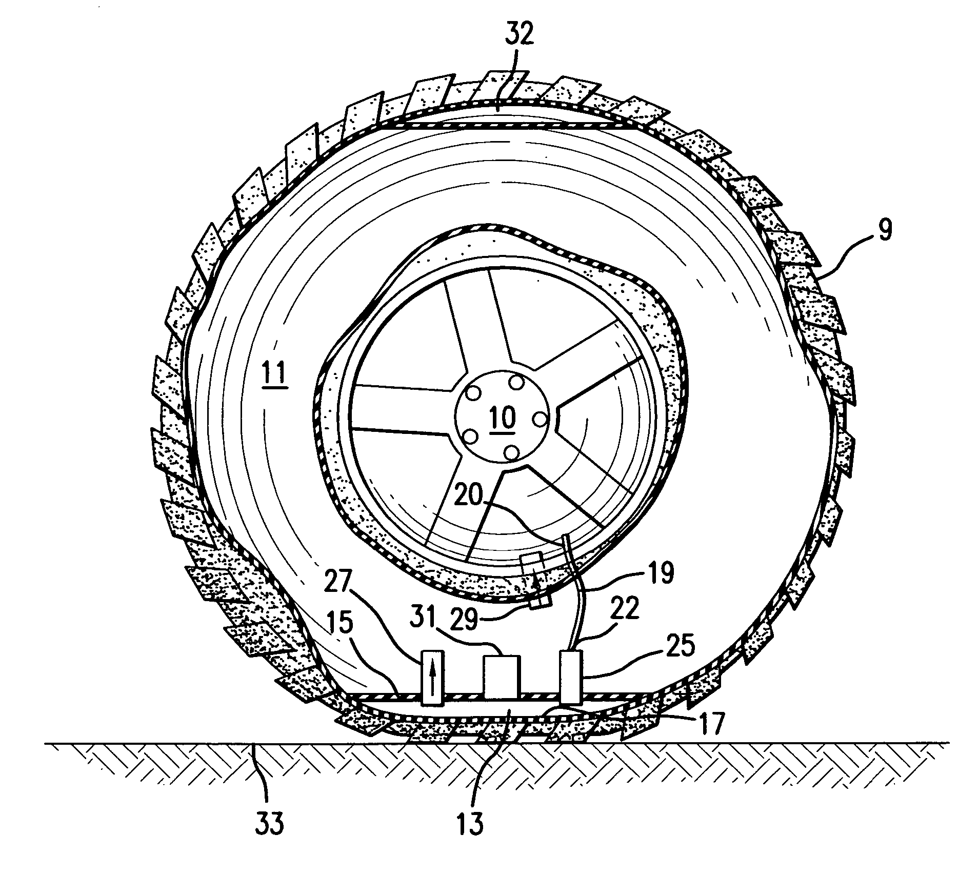
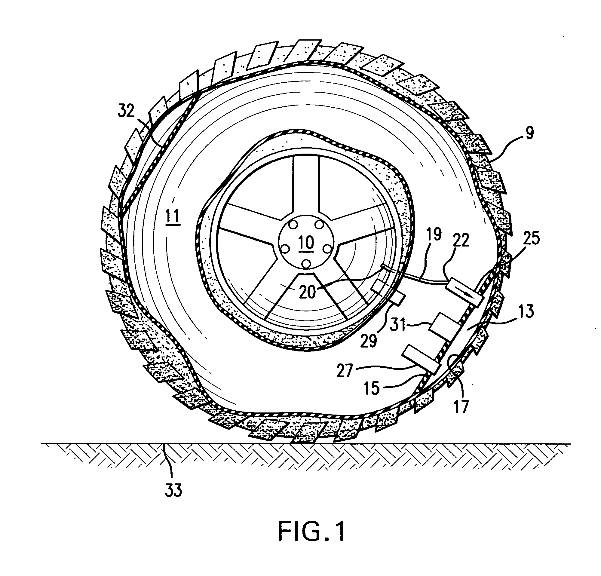
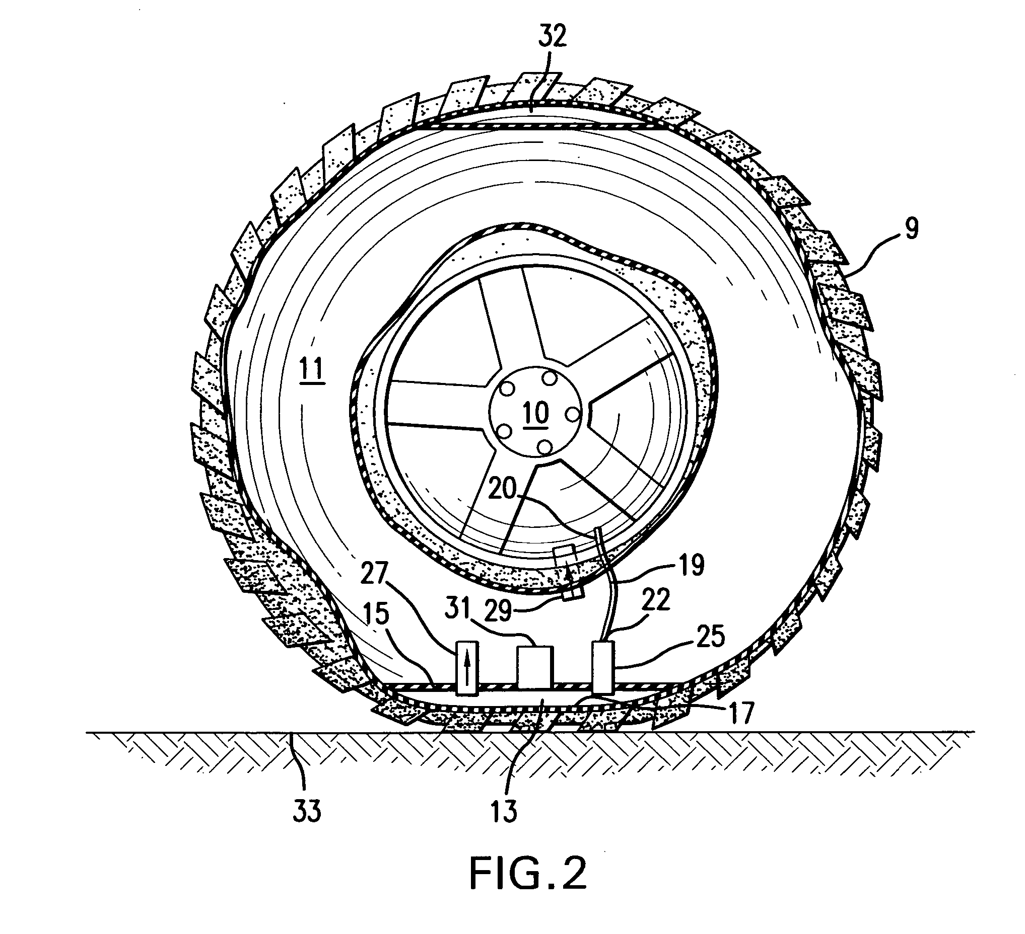
[0017] As seen in FIGS. 1-3, a pneumatic tire 9 mounted on a wheel 10 defines an outer or main chamber 11 serving as the larger operative volume of the tire 9 and which contains a compressible fluid such as air which is to be maintained at a specific pressure. An inner or pump chamber 13, serving as the compression or fluid pump means, is located within the tire 9 and adjacent the outer chamber 11. The pump chamber 13 comprises a rigid wall 15 providing an...


PUM


Abstract

An inflation and pressure regulation system for inflatable vessels, such as tires, has a main chamber containing a volume of compressible fluid, such as air, and a pump chamber which acts to maintain the fluid in the vessel at a desired pressure. The pump chamber has a rigid, fluid-tight wall facing the main chamber and a flexible wall which is part of, or adjacent to, the wall of the vessel that can be deformed under use. A fluid channel extending between the pump chamber and a source of ambient fluid admits fluid into the pump chamber. A first check valve positioned between the fluid channel and the pump chamber permits one-way flow of fluid from the exterior of the vessel into the pump chamber while it is uncompressed. A second check valve permits one-way passage of fluid from the pump chamber, when it is compressed, into the main chamber. One or more valves can be used to prevent over-inflation of the main chamber.

Description

[0001] This Patent Application claims priority to U.S. Provisional Application No. 60 / 591,823; filed 28 Jul. 2004.BACKGROUND OF THE INVENTION [0002] It is essential to maintain correct air pressure within vehicle tires for their safe and efficient operation and the maximal life of the tires. Current methods of pressure regulation require periodic monitoring and correction of the pressure, which is usually accomplished by manual methods. If the measured pressure is low, air is normally provided by an external supply of compressed air or directly from a pump. These manual methods are tedious, require regular attention, and are often neglected. Under-inflation of tires compromises safety, fuel efficiency, and tread life. [0003] Similar manual methods are used to maintain pressure within other vessels such as sporting balls, e.g., soccer balls, basketballs, footballs, and other air or fluid filled vessels. The balls regularly need to be pumped up by external means, which is a nuisance. ...

Claims


Application Information

Patent Timeline
Patent Type & Authority Applications(United States)
IPC IPC(8): B60C23/10
CPCB60C23/12B60C23/124B60C23/135
Inventor BUNKER, GRANT
Owner BUNKER GRANT
Why Eureka
Try Eureka