Vehicle obstacle warning radar

a technology of obstacle warning and radar, which is applied in the field of radar systems, can solve the problems of increasing the difficulty of determining the angle and range of obstacles, and driving behind the vehicle may not be able to see the obstacles located to the side or front of the vehicle, and the driver may not be able to see the obstacles properly

Inactive Publication Date: 2006-02-02
OHIO STATE INNOVATION FOUND
View PDF77 Cites 92 Cited by
  • Summary
  • Abstract
  • Description
  • Claims
  • Application Information

AI Technical Summary

Problems solved by technology

Compounding the problem with the blind spot, some drivers may not see properly behind the vehicle simply because they are distracted or do not exercise proper care.
For many of the same or similar reasons, a driver may not be able to see obstacles located to the side or front of a vehicle.
It should be recognized that the receiving antennas may be arranged in a non-linear configuration, but a non-linear configuration may increase the difficulty of determining the angle and range estimates of the obstacles.

Method used


Image

  • Vehicle obstacle warning radar
  • Vehicle obstacle warning radar
  • Vehicle obstacle warning radar

Examples


examples

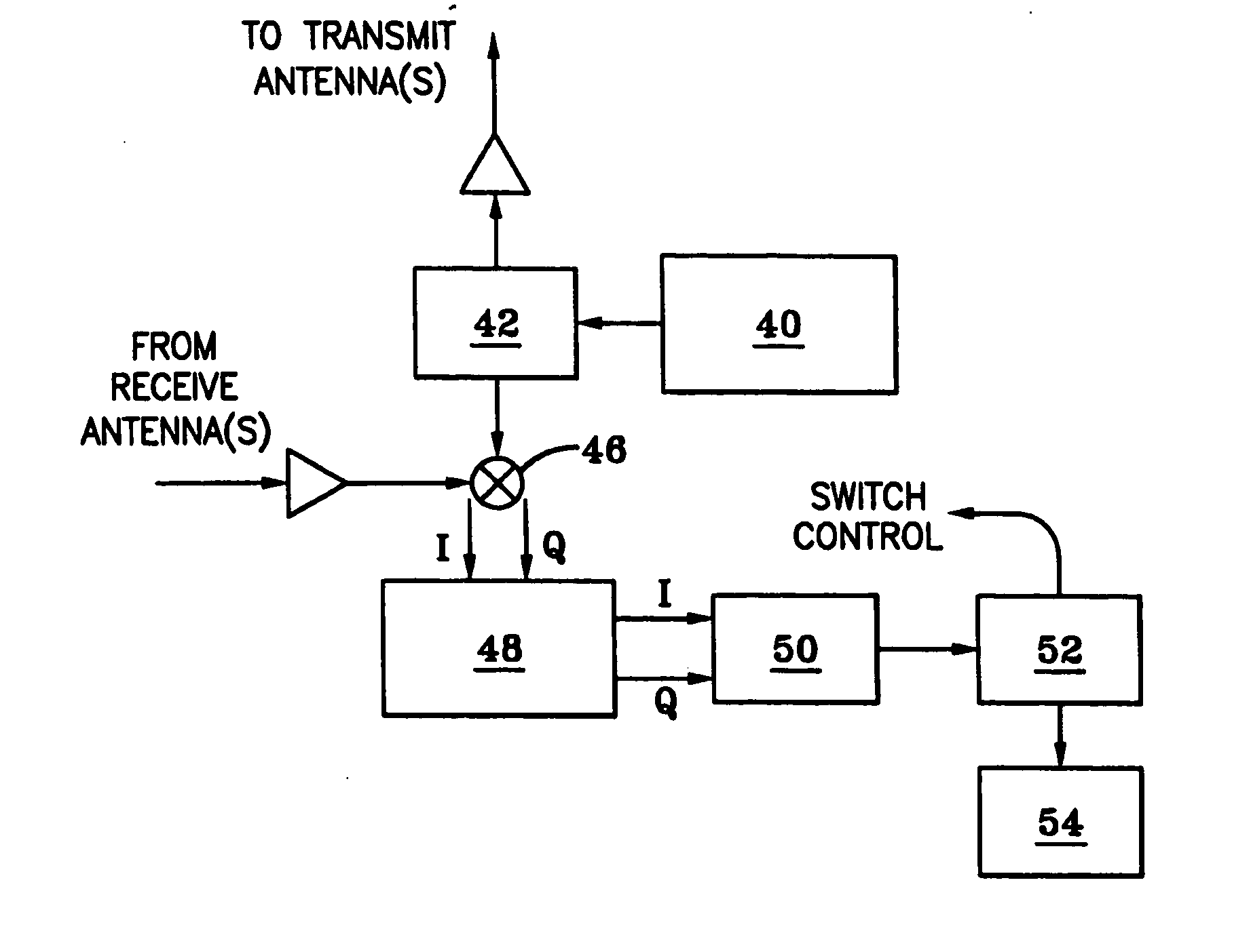
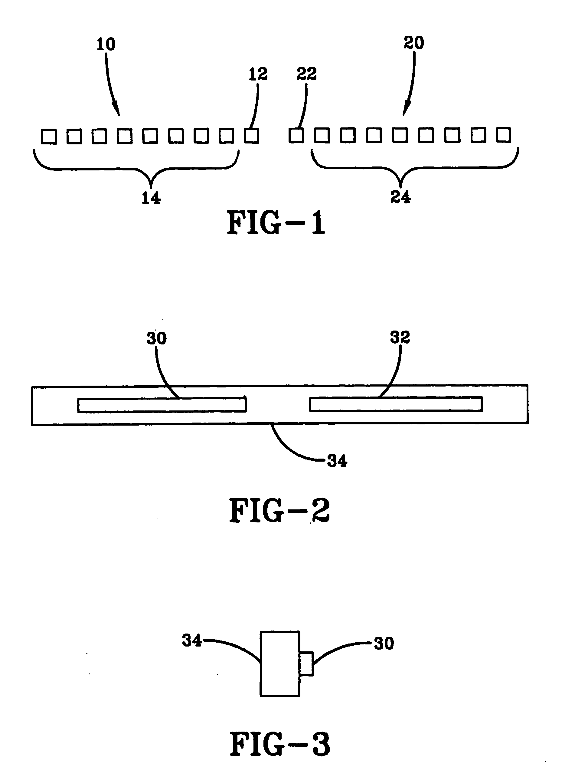
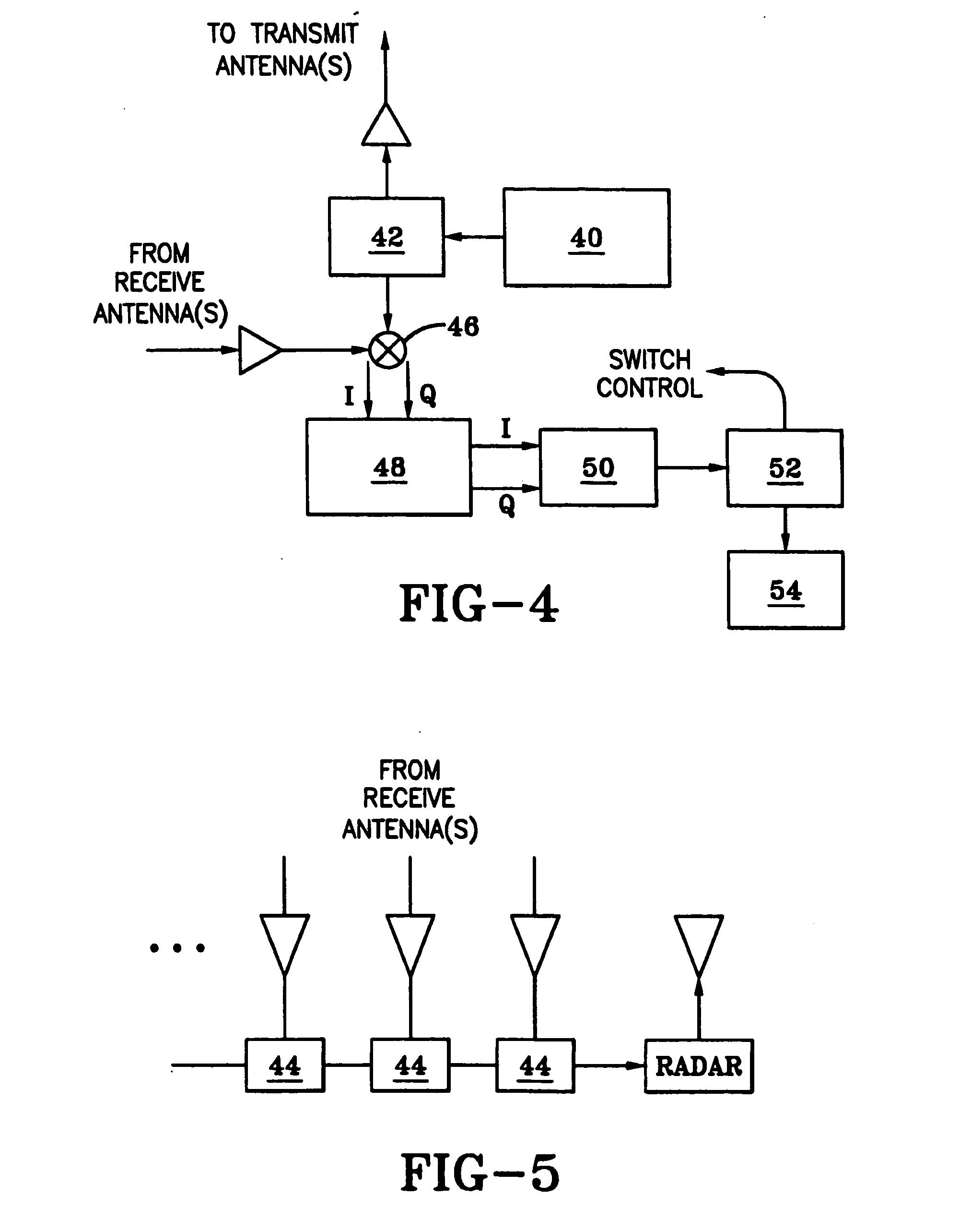
[0086] An exemplary embodiment of an X-band, dual-array radar system of the present invention was developed for detecting both stationary and moving objects within the configurable coverage area. In this example, each array receives microwave scattered signals whose magnitude and phase are recorded via a zero-IF, I / Q mixing scheme. The down-converted signals are then sampled and digitized using an analog-to-digital converter. Each receiving element is switched on using a fast, custom RF switch design. The received array information is then processed to obtain the angle-of-arrival (AOA) intensity profile whose high magnitude regions indicate the direction of possible obstacles. The AOA information from left and right arrays is then used to triangulate the locations of the obstacles. A custom radar control and data processing software program was also developed. The hardware designs and software operations of this example are described herein.

[0087] A reverse-sensing collision avoida...


PUM


Abstract

The present invention is a radar system for detecting the presence of obstacles. The radar system includes at least one transmitting antenna and at least one receiving antenna. The transmitting antenna receives an input signal and transmits an electromagnetic wave. The electromagnetic wave reflects off an obstacle back to the receiving antenna. The receiving antenna captures the reflected electromagnetic wave and produces an output signal. The output signal is then combined with the local reference signal in a quadrature mixer. The resulting in-phase (I) and quadrature (Q) signals may be further processed and then transmitted to a processing system. The processing system uses a suitable algorithm, e.g., a back projection algorithm, to estimate the type and location of obstacles that reflected the electromagnetic wave. In an exemplary embodiment, the algorithm is adapted to discriminate between different sizes and locations of obstacles in order to determine if there is a hazard. Based on this information, the processing system then communicates with a visual and / or audible warning system in order to alert the driver about the obstacle if it has been determined to be a hazard.

Description

[0001] This application is a continuation-in-part of U.S. application Ser. No. 10 / 294,507, filed Nov. 14, 2002, which claims the benefit of U.S. Provisional Application No. 60 / 349,816, filed Jan. 17, 2002, each of which is hereby incorporated by reference in its entirety.BACKGROUND AND SUMMARY OF THE INVENTION [0002] The present invention relates generally to a radar system and, more particularly, to a warning radar that may be used to detect obstacles in the path of a moving or stationary vehicle. Although the present invention will be described herein primarily with regard to a vehicle obstruction warning radar, it should be understood that the present invention may also be also be used in other applications. For instance, the present invention may be used in other similar or conventional applications of radars. [0003] A driver may check his rearview mirror and sideview mirrors when backing up a vehicle. A driver may also pivot his head around to look behind the vehicle. Despite c...

Claims


Application Information

Patent Timeline
Patent Type & Authority Applications(United States)
IPC IPC(8): G01S13/93G01S7/28G01S7/288G01S7/35G01S13/00G01S13/02G01S13/32G01S13/42G01S13/87G01S13/931
CPCG01S3/48G01S2013/9385G01S7/352G01S13/003G01S13/32G01S13/46G01S13/931G01S2007/358G01S2013/0245G01S2013/0254G01S2013/9332G01S2013/9389H01Q1/3233H01Q1/3283H01Q9/0407H01Q21/08H01Q23/00G01S2007/4086G01S2013/9375G01S5/04G01S2013/9315G01S2013/93275G01S2013/93274G01S2013/93271G01S7/358G01S7/4086
Inventor WALTON, ERIC K.CHEN, CHI-CHIH
Owner OHIO STATE INNOVATION FOUND
Why Eureka
Try Eureka