Compact front-operable image forming apparatus

a front-operated, compact technology, applied in the direction of recording apparatus, instruments, electrographic processes, etc., can solve the problems of difficult top face use, difficult top face loading, paper feed tray and paper discharge tray handling, etc., to achieve the effect of not increasing the footprin

Inactive Publication Date: 2006-02-02
RICOH KK
View PDF12 Cites 25 Cited by
  • Summary
  • Abstract
  • Description
  • Claims
  • Application Information

AI Technical Summary

Benefits of technology

[0030] Since the transport cover is detachable and has the storage unit formed thereon, the image forming apparatus can store miscellaneous objects therein without increasing its footprint.

Problems solved by technology

However, if the top face of the image forming apparatus is simply made wide and flat, the top face may give a negative visual impression to the user.
If the top face of the image forming apparatus is simply made wide, the loading of the paper feed tray and the handling of paper discharged into the paper discharge tray may become difficult.
If operations keys and displays are provided on the top face, it becomes difficult to use the top face effectively, even if the top face is made large.
However, it is not cost-effective to design the image forming apparatus body to support heavy weight.
However, if paper is fed from the rear and discharged to the front of the image forming apparatus, even if the image forming apparatus body is made compact, the total system becomes considerably larger.
It would be difficult to dispose it on a desk or in a rack.
It is difficult to dispose the image forming apparatus on a desk or in a rack.
It becomes difficult to handle the paper feed tray while replenishing with paper.
However, if paper is reversed at a short radius, the paper tends to roll up in the transport directions, which may make the discharging of the paper difficult.
Likewise, if the paper discharge tray is disposed below the opening to some extent, the paper drops in the paper discharge tray with its top rolled up due to its weight, which makes the discharging of the paper difficult.

Method used


Image

  • Compact front-operable image forming apparatus
  • Compact front-operable image forming apparatus
  • Compact front-operable image forming apparatus

Examples


Embodiment Construction

[0089] A description of the embodiments of the present invention is given below with reference to the drawings.

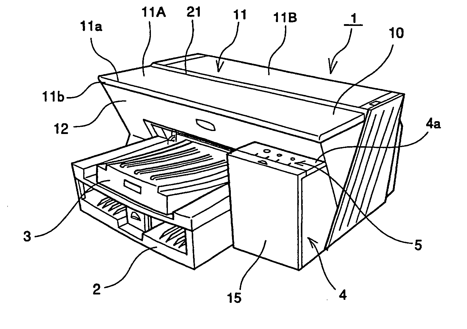
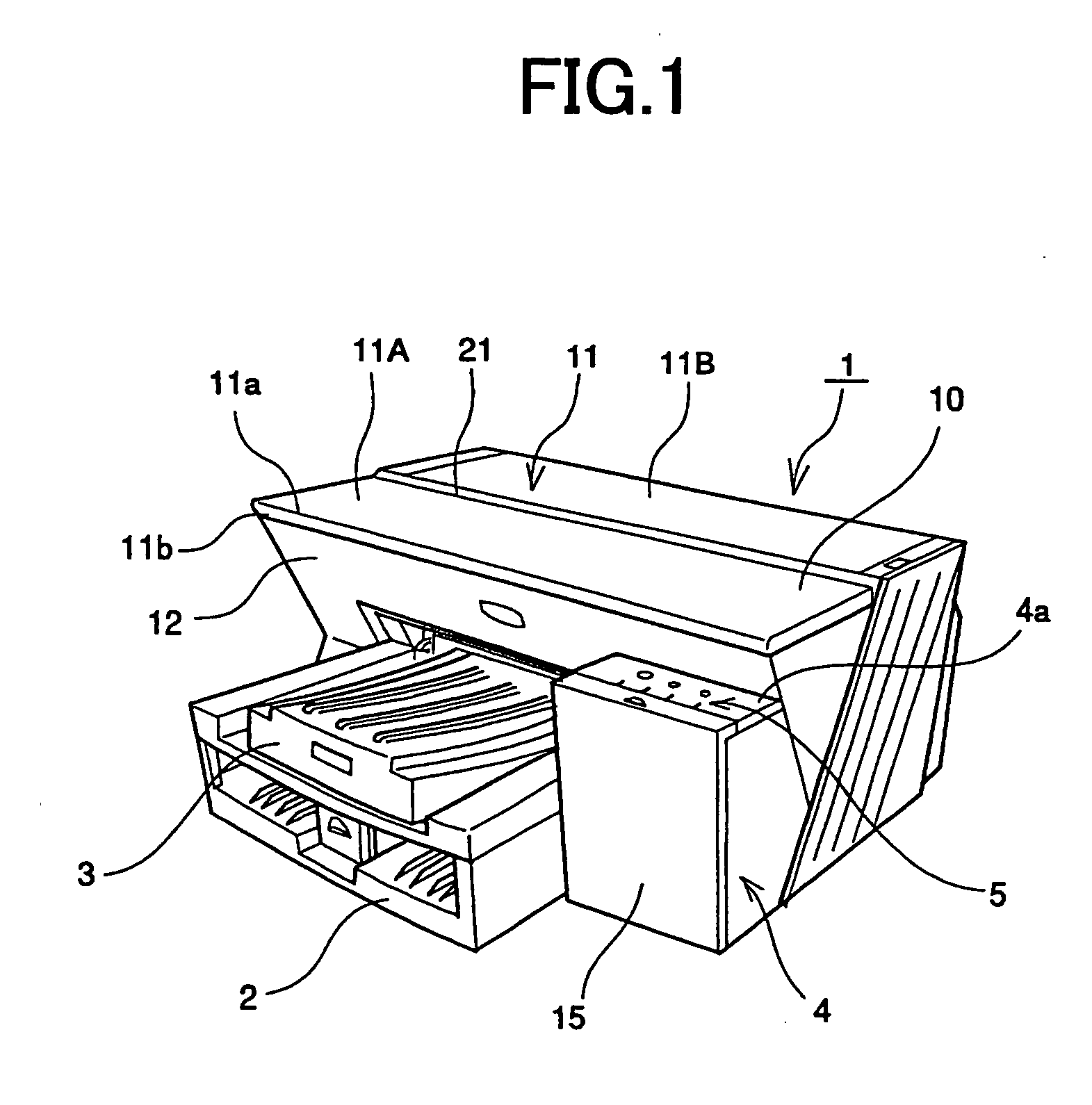
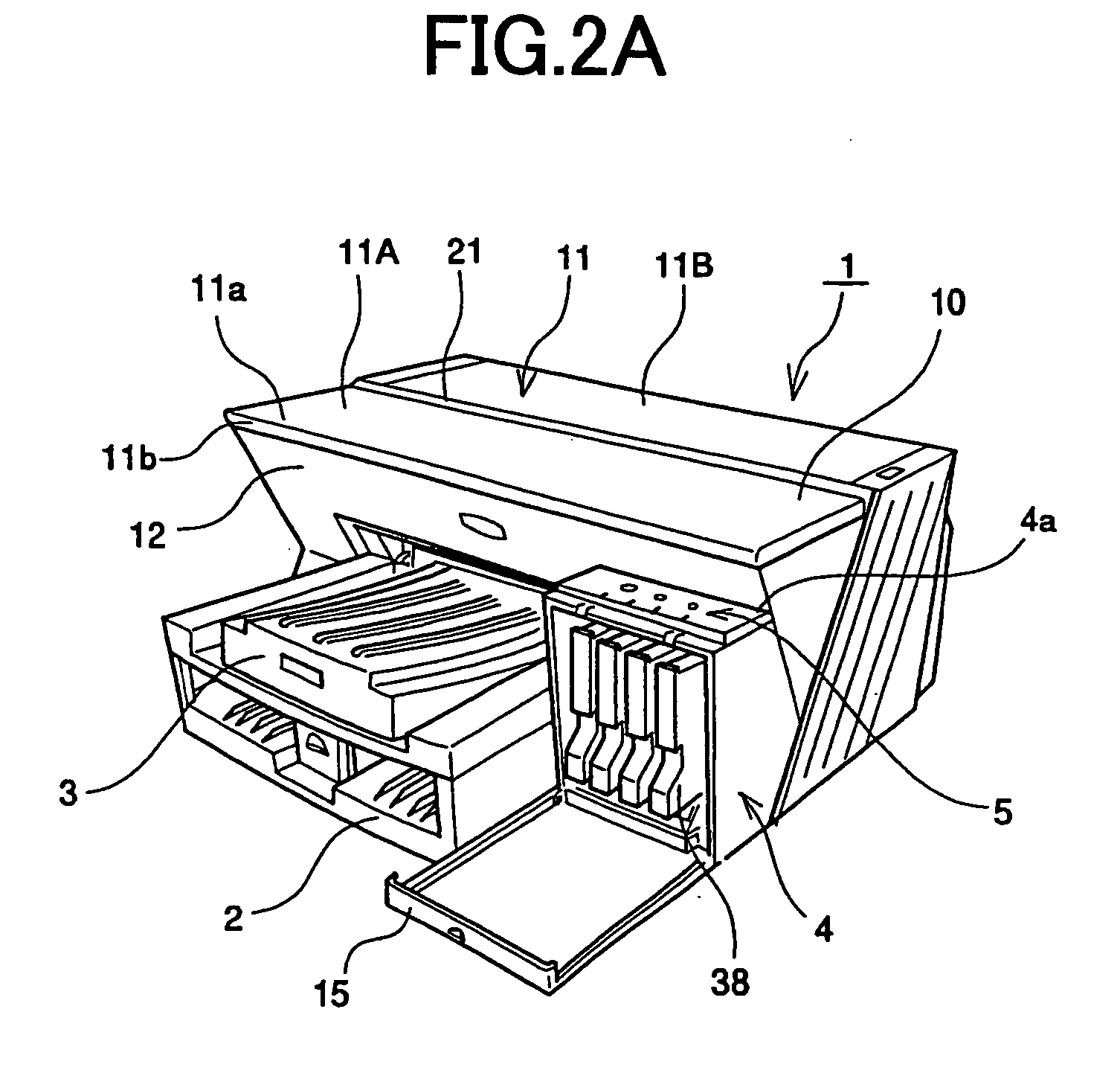
[0090]FIG. 1 is a perspective view showing from front an ink jet recording apparatus including a paper discharge tray according to an embodiment. FIG. 2A is a perspective view showing the ink jet recording apparatus according to the embodiment with its ink cartridge loading unit open. FIG. 2B is a perspective view showing the ink jet recording apparatus according to the embodiment for explaining the loading of an ink cartridge. FIG. 3 is a perspective view showing from the rear the ink jet recording apparatus according to the embodiment.

[0091] The ink jet recording apparatus includes an apparatus body 1, a paper feed tray 2, and a paper discharge tray 3. The paper feed tray 2 is loaded on the apparatus body 1 and feeds paper. The paper discharge tray 3 is also loaded on the apparatus body 1, and paper on which images are formed is stacked on the paper discharge tray 3.

[0...


PUM


Abstract

An image forming apparatus is disclosed that includes a substantially flat top face and a slanted front face, the bottom side of which recedes backward. The image forming apparatus may includes a paper discharge tray disposed at a lower portion of the slanted front face, the paper discharge tray protruding forward. The paper discharge tray may be tiltable upward and downward. Because the bottom side of the slanted front face recedes backward, the flat top face can be provided, and simultaneously, enough space for the feeding and discharging of paper can be secured.

Description

TECHNICAL FIELD [0001] The present invention generally relates to an image forming apparatus, and more particularly, to a useful compact front-operable image forming apparatus and a paper discharge tray of the same. BACKGROUND ART [0002] Image forming apparatuses includes printers, facsimile machines, and copiers, for example. [0003] Ink jet image forming apparatuses (ink jet recording apparatuses) are known as a kind of image forming apparatus. The ink jet recording apparatus records images on a recording medium such as paper and transparent plastic sheets for OHP, by discharging ink droplets from a recording head thereof. The advantages of the ink jet recording apparatus include low running cost, low noise, and easy color printing using multiple color inks. [0004] Electrophotography image forming apparatuses are known as another kind of image forming apparatus. The electrophotography image forming apparatus forms toner images on a photosensitive unit using a charging unit, an expo...

Claims


Application Information

Patent Timeline
Patent Type & Authority Applications(United States)
IPC IPC(8): B41J2/01B41J13/00B41J2/175B41J13/10B41J29/02B41J29/13B65H1/26B65H31/00B65H31/20G03G15/00
CPCB41J2/17509B41J2/1752B41J29/13B41J2/17553B41J13/106B41J2/1755
Inventor KATSUYAMA, GOROKABUMOTO, MASSAKIAMEMIYA, KANAEMIKI, OSAMUAOKI, HIDEOTANAKA, AKIYOSHI
Owner RICOH KK
Why Eureka
Try Eureka