Omni-directional camera with calibration and up look angle improvements

a technology of omni-directional cameras and calibration, applied in the field of camera design, can solve the problems of high cost, and limited resolution of single sensor designs

Active Publication Date: 2006-02-02
MICROSOFT TECH LICENSING LLC
View PDF67 Cites 44 Cited by
  • Summary
  • Abstract
  • Description
  • Claims
  • Application Information

AI Technical Summary

Benefits of technology

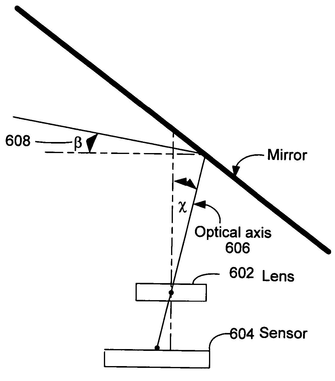
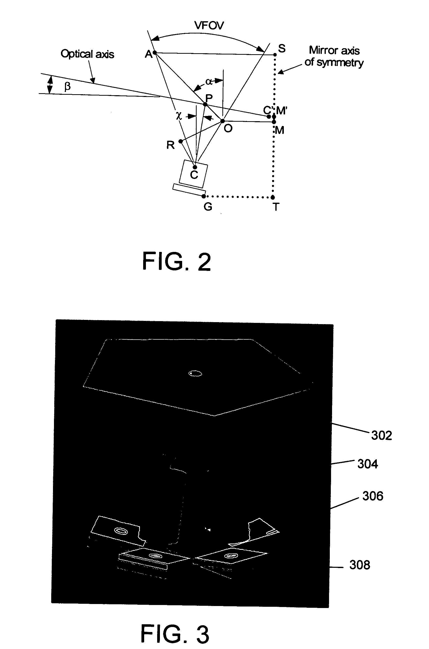
[0007] The camera system and method of the present invention provides an improved up look angle (meaning the chief ray points above the horizon) to capture more of the desired subject matter and an improved method for calibrating a virtual center of projection between adjacent cameras in a multi-sensor camera design.
[0008] One embodiment of the invention is an improvement over the camera system described in co-pending patent application Ser. No. 10 / 608,363, entitled “OMNI-DIRECTIONAL CAMERA DESIGN FOR VIDEO CONFERENCING”, filed on Jun. 26, 2003. This camera system uses N cameras and an N-sided mirror to capture images of the surrounding scene. The images from the N cameras are stitched together to create a 360-degree panorama using a calibration surface. The present invention extends the camera system described in the aforementioned co-pending patent application to improve manufacturability in two ways. First, by using a view camera technique to achieve an up look angle, the image sensors can be mounted flat to a printed circuit board (PCB). Secondly, by using a sub-region of the image sensor for the active area the camera system of the invention allows for the electronic calibration of each camera's virtual center of projection (C′) and provides boresighting. Boresighting typically aligns the lens optical axis with the image sensor center. In system and method according to the invention the term boresighting includes a prescribed image sensor location that is shifted from the center. Using the sensor sub-region eliminates two degrees of freedom from mechanical calibration.
[0011] Thus, the camera system and method according to the invention is advantageous in that it is lower cost, easier to calibrate and easier and less expensive to manufacture achieved by mounting the image sensors on a flat surface. This configuration images less of the table, and allows imaging of people standing near the table, or sitting around it, at higher resolutions. This configuration maximizes the use of the imaging sensors, further reducing cost of the system. More specifically, cameras with a smaller vertical field of view can be used as almost the entire field of view captures the video conference participants' faces and not extraneous data such as the surface the camera is sitting on. Cameras with a larger field of view require higher resolution sensors to achieve similar performance.

Problems solved by technology

Single sensor designs are limited in resolution by the image sensor, and are typically more expensive than multi-sensor designs.
Their resolution and frame rate are also typically limited.
In addition, the curved mirror designs used in these single sensor designs have typically suffered from a limited depth of field.
These multi-sensor designs can often be difficult to calibrate and manufacture however.

Method used


Image

  • Omni-directional camera with calibration and up look angle improvements
  • Omni-directional camera with calibration and up look angle improvements
  • Omni-directional camera with calibration and up look angle improvements

Examples


Embodiment Construction

[0023] In the following description of the preferred embodiments of the present invention, reference is made to the accompanying drawings that form a part hereof, and in which is shown by way of illustration specific embodiments in which the invention may be practiced. It is understood that other embodiments may be utilized and structural changes may be made without departing from the scope of the present invention.

1.0 Exemplary Operating Environment

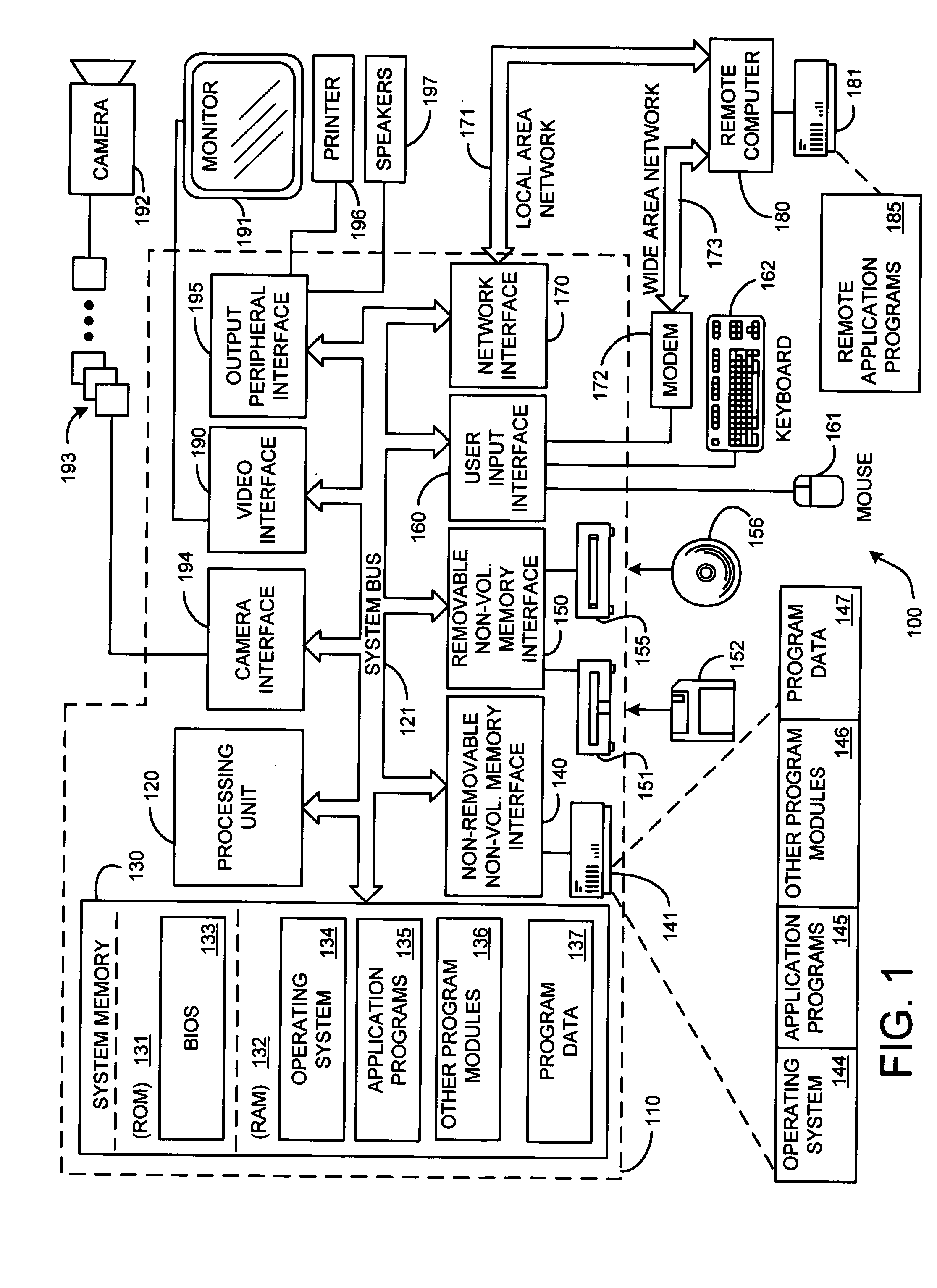
[0024]FIG. 1 illustrates an example of a suitable computing system environment 100 on which the invention may be implemented. The computing system environment 100 is only one example of a suitable computing environment and is not intended to suggest any limitation as to the scope of use or functionality of the invention. Neither should the computing environment 100 be interpreted as having any dependency or requirement relating to any one or combination of components illustrated in the exemplary operating environment 100.

[0025] The i...


PUM


Abstract

Improved camera calibration techniques, including an improved up look angle and an improved method for calibrating a virtual center of projection. By using a view camera technique for the up look angle, the image sensors can be mounted flat to a Printed Circuit Board (PCB). By using a sub-region of the image sensor for the active area of the camera it is possible to calibrate the virtual center of projection (C′).

Description

BACKGROUND [0001] 1. Technical Field [0002] This invention is directed toward a new camera design. More specifically, this invention is directed toward a camera design with an improved up look angle and an improved ability to calibrate a virtual center of projection. [0003] 2. Background Art [0004] Video conferencing has become more popular in recent years. Various video conferencing camera systems have been developed for this purpose. In many video conferencing scenarios an omni-directional camera is placed in the middle of a conference room table. This camera captures images of the meeting participants sitting around the table for transmission to a remote site or later play back of the meeting for those unable to attend. [0005] There are two general categories of omni-directional or panoramic video cameras: single sensor and multiple sensor designs. Single sensor omni-directional cameras use multiple mirrors to image a 360 degree horizontal field of view onto an image sensor. Sing...

Claims


Application Information

Patent Timeline
Patent Type & Authority Applications(United States)
IPC IPC(8): H04N5/225H04N5/76G03B37/00G03B37/04
CPCG06T7/0018H04N5/23238H04N5/2259G06T7/80H04N23/58H04N23/698
Inventor CUTLER, ROSS
Owner MICROSOFT TECH LICENSING LLC
Why Eureka
Try Eureka