Single-stage constant-speed valve used for high-pressure kerosene constant-speed hydraulic motor

A technology of hydraulic motor and kerosene, which is applied to fluid pressure actuating devices, mechanical equipment, servo motor components, etc., can solve the problems of high processing cost and complex structure, and achieve the effect of low processing cost, easy operation and high integration.

Active Publication Date: 2016-06-01
BEIJING RES INST OF PRECISE MECHATRONICS CONTROLS +1
View PDF7 Cites 2 Cited by
  • Summary
  • Abstract
  • Description
  • Claims
  • Application Information

AI Technical Summary

Problems solved by technology

[0005] At present, the constant speed valve used on the 20kW constant speed kerosene hydraulic motor driven by high pressure and large flow kerosene is a two-stage constant speed valve, which can realize the constant speed control of high power kerosene hydraulic motor, but the structure is complex and the processing cost is high

Method used


Image

  • Single-stage constant-speed valve used for high-pressure kerosene constant-speed hydraulic motor
  • Single-stage constant-speed valve used for high-pressure kerosene constant-speed hydraulic motor
  • Single-stage constant-speed valve used for high-pressure kerosene constant-speed hydraulic motor

Examples


specific Embodiment 1

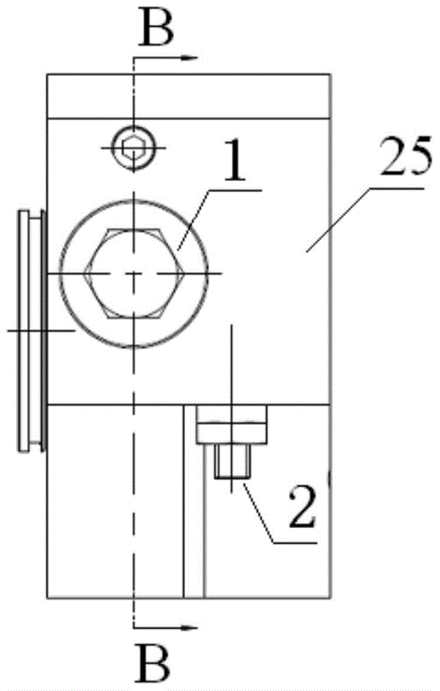
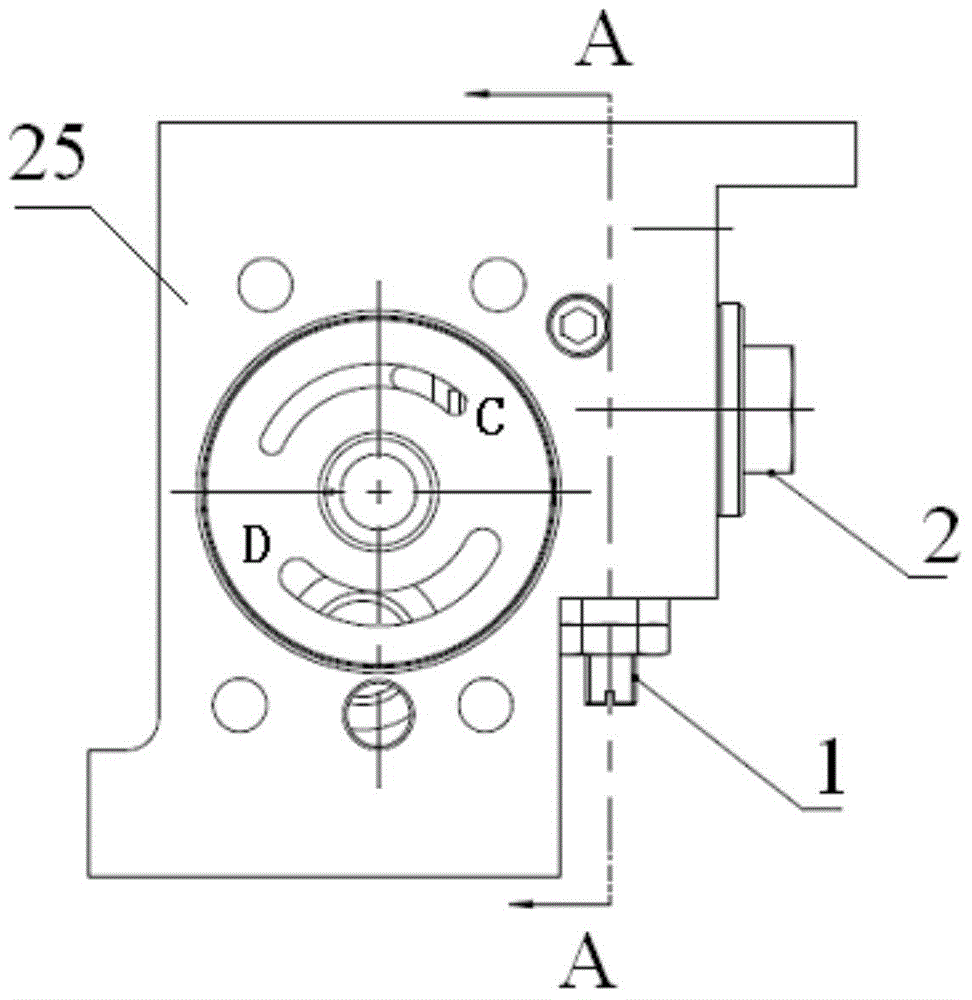
[0040] figure 2 , 3 , 4 and 5 are schematic diagrams of a single-stage constant-speed valve applied to a high-pressure kerosene constant-speed hydraulic motor with a two-valve cross-arrangement structure provided by the present invention. In this embodiment, the cavity where the throttle valve 1 is located and the compensation valve The cavities where 2 are located are perpendicular to each other. Both the throttle valve 1 and the compensation valve 2 are located in the valve housing 25 .

[0041] like Figure 4As shown, the throttle valve 1 includes an adjusting screw 7, a lock nut 8, a screw sleeve 9, a card seat 10, a guide pin 11, a throttle valve core 12, a spring I13, a spring seat I14, and an anti-rotation pin 24. The throttle valve 1 is installed in the valve housing 25 . The spring seat I14 is fixed at the end of the valve housing 25 close to the inlet H of the throttle valve 1 through threads. One end of the spring I13 is located in the spring seat I14, and the...

specific Embodiment 2

[0044] Image 6 , 7 , 8 and 9 are schematic diagrams of a single-stage constant-speed valve applied to a high-pressure kerosene constant-speed hydraulic motor provided by the two-valve parallel arrangement structure. In this embodiment, the cavity where the throttle valve 1 is located and the compensation valve The cavities where 2 are located are parallel to each other. Both the throttle valve 1 and the compensation valve 2 are located in the valve housing 25 .

[0045] like Figure 8 As shown, the throttle valve 1 includes an adjusting screw 7, a lock nut 8, a screw sleeve 9, a card seat 10, a guide pin 11, a throttle valve core 12, a spring I13, a spring seat I14, and an anti-rotation pin 24. The throttle valve 1 is installed in the valve housing 25 . The spring seat I14 is fixed at the end of the valve housing 25 close to the inlet H of the throttle valve 1 through threads. One end of the spring I13 is located in the spring seat I14, the spring I13 is sleeved on the s...


PUM


Abstract

The invention belongs to a constant-speed valve and relates to a single-stage constant-speed valve used for a high-pressure kerosene constant-speed hydraulic motor, in particular to a high-reliability integrated large-flow single-stage constant-speed valve used for a constant-speed hydraulic motor driven by high-pressure kerosene. The single-stage constant-speed valve comprises a valve shell, a throttle valve and a compensation valve. The throttle valve is fixed in a cavity inside the valve shell. The compensation valve is fixed in the other cavity inside the valve shell. In the valve shell, an outlet of the cavity where the throttle valve is located communicates with an inlet of the cavity where the compensation valve is located. A damping hole is formed in the valve shell and enables an inlet of the cavity where the throttle valve is located to communicate with the cavity where the compensation valve is located. The single-stage constant-speed valve is simple in structure, high in reliability, low in machining cost, easy to assemble and adjust, high in integration level, capable of fixing and controlling the steady state rotation speed difference, and easy to operate.

Description

technical field [0001] The invention relates to a single-stage constant-speed valve for a high-pressure kerosene constant-speed hydraulic motor, in particular to a high-reliability integrated large-flow single-stage constant-speed valve for a high-pressure kerosene-driven constant-speed hydraulic motor. Background technique [0002] The high pressure kerosene constant speed hydraulic motor is the power element in the servo mechanism of the liquid oxygen kerosene engine launch vehicle. The LOX kerosene engine uses liquid oxygen and kerosene as fuel, and has the advantages of non-toxic, non-polluting, cost-effective, and easy to use and maintain. It is currently a mainstream launch vehicle engine in the world. Correspondingly, the servo mechanism of the swinging liquid oxygen kerosene engine is also a must-have equipment on the arrow. The high-pressure kerosene constant-speed hydraulic motor is the component that provides reliable power for the servo mechanism at a relatively...

Claims


Application Information

Patent Timeline
Patent Type & Authority Applications(China)
IPC IPC(8): F15B13/02
Inventor 于斌刘会祥王伟
Owner BEIJING RES INST OF PRECISE MECHATRONICS CONTROLS
Why Eureka
Try Eureka