Microseismic fracture mapping using seismic source timing measurements for velocity calibration

a microseismic fracture and timing measurement technology, applied in seismology for waterlogging, transmission monitoring, instruments, etc., can solve the problems of large amount of shear stress, shear slippage, and low permeability to effectively produce gas in economic quantities

Active Publication Date: 2006-02-02
HALLIBURTON ENERGY SERVICES INC
View PDF86 Cites 63 Cited by
  • Summary
  • Abstract
  • Description
  • Claims
  • Application Information

AI Technical Summary

Problems solved by technology

In many gas fields, permeability is too low to effectively produce gas in economic quantities.
Fractures are often created in this process that direct the oil in a potentially unknown direction.
Large tensile stresses are formed ahead of the crack tip, which creates large amounts of shear stress.
Both mechanisms, pore pressure increase and formation stress increase, affect the stability of planes of weakness (such as natural fractures and bedding planes) surrounding the hydraulic fracture and cause them to undergo shear slippage.
However, multiple offset wells are not usually available.
However, the precise length, direction, and height of the created fractures will not be obtainable unless the microseismic events are accurately detected from beginning to end.

Method used


Image

  • Microseismic fracture mapping using seismic source timing measurements for velocity calibration
  • Microseismic fracture mapping using seismic source timing measurements for velocity calibration
  • Microseismic fracture mapping using seismic source timing measurements for velocity calibration

Examples


Embodiment Construction

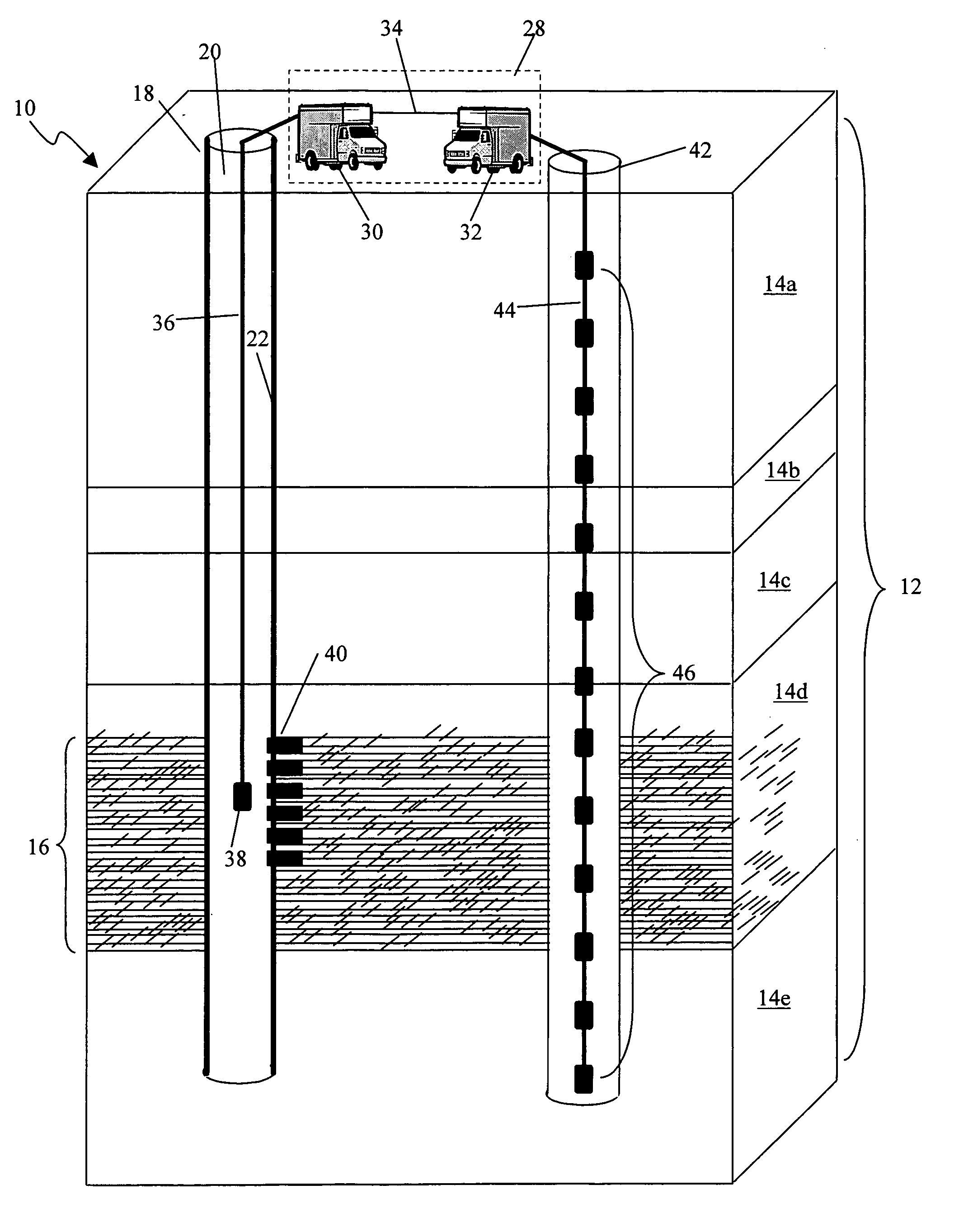
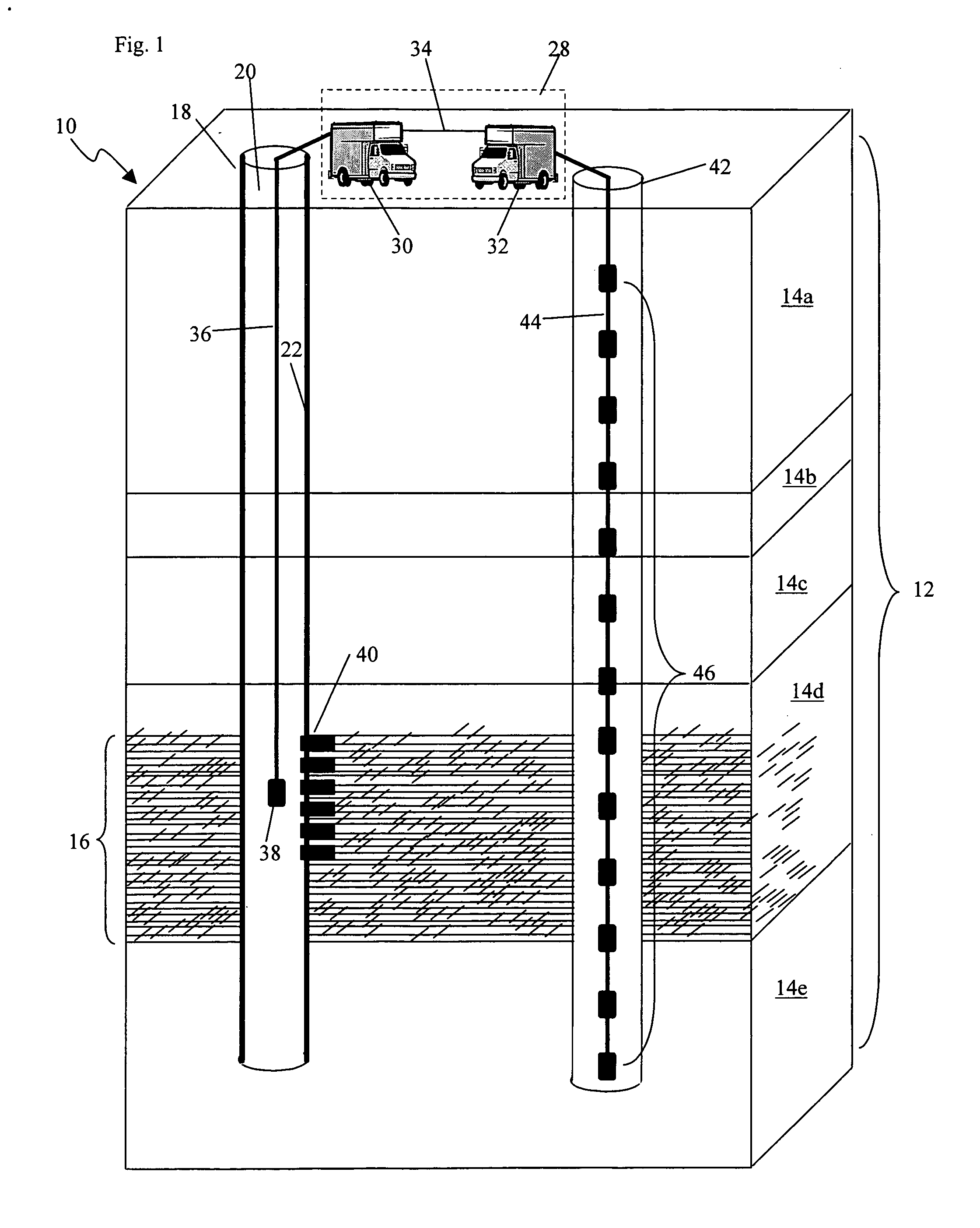
[0012] The invention relates to microseismic events and, more particularly, to a method for the in situ determination of the distribution and orientation of fractures in subterranean formations. It is understood, however, that the following disclosure provides many different embodiments or examples. Specific examples of components and arrangements are described below to simplify the present disclosure. These are, of course, merely examples and are not intended to be limiting. In addition, the present disclosure may repeat reference numerals and / or letters in the various examples. This repetition is for the purpose of simplicity and clarity and does not in itself dictate a relationship between the various embodiments and / or configurations discussed. Further, the drawings are used to facilitate the present disclosure, and are not necessarily drawn to scale.

[0013] Referring now to FIG. 1, a partial cutaway view 10 is shown with a treatment well 18 that extends downward into strata 12,...


PUM


Abstract

A system and method for microseismic fracture mapping using seismic source timing measurements for velocity calibration is disclosed. The system may include a seismic source coupled to a wireline and a seismic source trigger, a sensor capable of detecting a first signal from the seismic source trigger, a transmitter coupled to the sensor, capable of transmitting a time value associated with the first signal, a receiver capable of detecting an event generated by the seismic source; and an analyzer capable of calculating a microseismic velocity of the event. In one embodiment, a first signal is transmitted through a wireline to trigger a seismic source. The first signal is detected, and a first time value associated with the first signal is transmitted. An event associated with the seismic source is detected and a second signal associated with the event is transmitted to an analyzer. A microseismic velocity is calibrated based on the time difference between the first time value and a second time value associated with the second signal.

Description

CROSS REFERENCE TO RELATED APPLICATIONS [0001] This patent application is a non-provisional of U.S. Provisional Patent Application No. 60 / 564,055, filed on Apr. 21, 2004, and entitled “Microseismic Fracture Mapping Using Seismic Source Timing Measurements For Velocity Calibration,” which is incorporated by reference herein in its entirety.FIELD OF THE INVENTION [0002] This invention relates generally to microseismic events and, more particularly, to a method for the in situ determination of the distribution and orientation of fractures in subterranean formations. BACKGROUND OF THE INVENTION [0003] Seismic data is used in many scientific fields to monitor underground events in subterranean rock formations. In order to investigate these underground events, micro-earthquakes, also known as microseisms, are detected and monitored. Like earthquakes, microseisms emit elastic waves—compressional (“p-waves”) and shear (“s-waves”), but they occur at much higher frequencies than those of eart...

Claims


Application Information

Patent Timeline
Patent Type & Authority Applications(United States)
IPC IPC(8): H04B17/00G01V1/00G01V1/40
CPCG01V1/40G01V1/008
Inventor UHL, JAMES E.WRIGHT, CHRISDAVIS, ERICWARD, JAMESWARPINSKI, NORMAN
Owner HALLIBURTON ENERGY SERVICES INC
Why Eureka
Try Eureka