Moving picture encoding/transmission system, moving picture encoding/transmission method, and encoding apparatus, decoding apparatus, encoding method decoding method and program usable for the same

a technology of encoding/transmission system and encoding/transmission method, which is applied in the field of moving picture encoding/transmission system, moving picture encoding/transmission method, encoding apparatus, encoding method decoding method and program usable for the same, can solve the problems of increasing the number, unable to perform efficient coding, and inability to set a plurality of macro block modes in one macro block, etc., to achieve the effect of suppressing the deteriorating

Active Publication Date: 2004-11-25
NTT DOCOMO INC
View PDF3 Cites 131 Cited by
  • Summary
  • Abstract
  • Description
  • Claims
  • Application Information

AI Technical Summary

Benefits of technology

0289] The loop filter 73 serves to suppress the deterioration such as the distortion of the sub-block, by performing filtering in sub-blocks for the result sent by the hybrid prediction decoding section 71.

Problems solved by technology

However, the conventional video coding transmission system cannot set a plurality of the "macro block mode" in one macro block.
Accordingly, there was a problem in that efficient coding cannot be performed when one macro block includes a portion (bird portion) which should be subjected to coding with the "intra-frame prediction mode" and a portion (cloud portion) which should be subjected to coding in the "inter-frame prediction mode", as shown in FIG. 4.
However, this method increases the number of macro blocks and then increases the number of transmissions of the coding information of each macro block necessary for coding, which causes a problem that reduces the coding efficiency.

Method used


Image

  • Moving picture encoding/transmission system, moving picture encoding/transmission method, and encoding apparatus, decoding apparatus, encoding method decoding method and program usable for the same
  • Moving picture encoding/transmission system, moving picture encoding/transmission method, and encoding apparatus, decoding apparatus, encoding method decoding method and program usable for the same
  • Moving picture encoding/transmission system, moving picture encoding/transmission method, and encoding apparatus, decoding apparatus, encoding method decoding method and program usable for the same

Examples


embodiment 1

CONFIGURATION OF VIDEO CODING TRANSMISSION SYSTEM OF THE PRESENT INVENTION

[0111] A description will be given of the configuration of a video coding transmission system according to Embodiment 1 of the present invention with reference to the drawings. FIG. 5 is a block diagram showing the configuration of the video coding transmission system according to this embodiment.

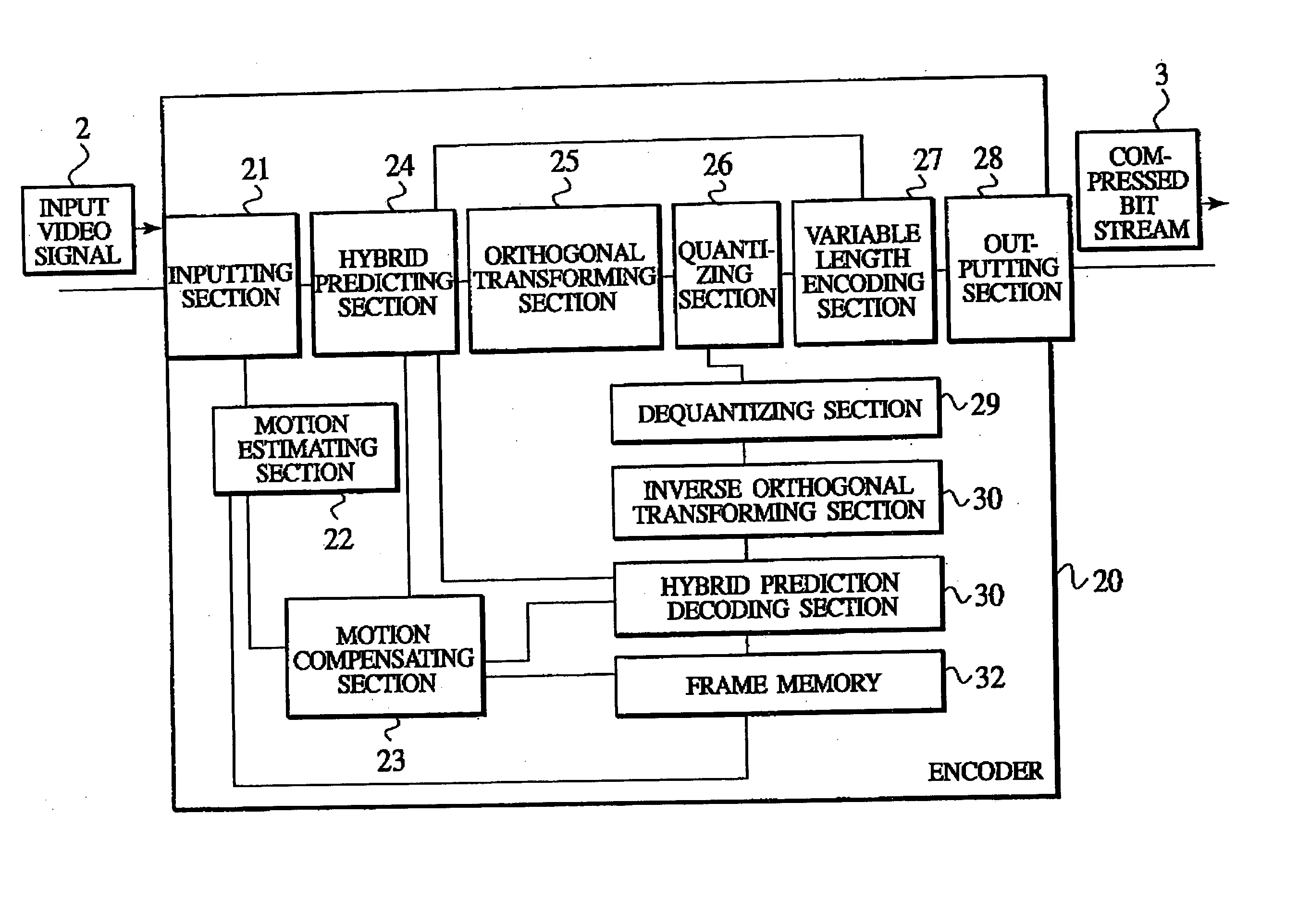
[0112] In the video coding transmission system according to this embodiment, an encoder 20 performs information compression and encoding process for an input video signal a which is a digital video, so as to obtain a "compressed bit stream 3", and transmits the compressed bit stream 3 to a decoder 40 via a network 1. In this video coding transmission system, the decoder 40 restores the compressed bit stream 3 so as to obtain an output video signal 4.

[0113] Herein, the network 1 is assumed to be various types of means which can receive and transmit the compressed bit stream 3, and is assumed to be, for example, a low-...

embodiment 2

CONFIGURATION OF VIDEO CODING TRANSMISSION SYSTEM

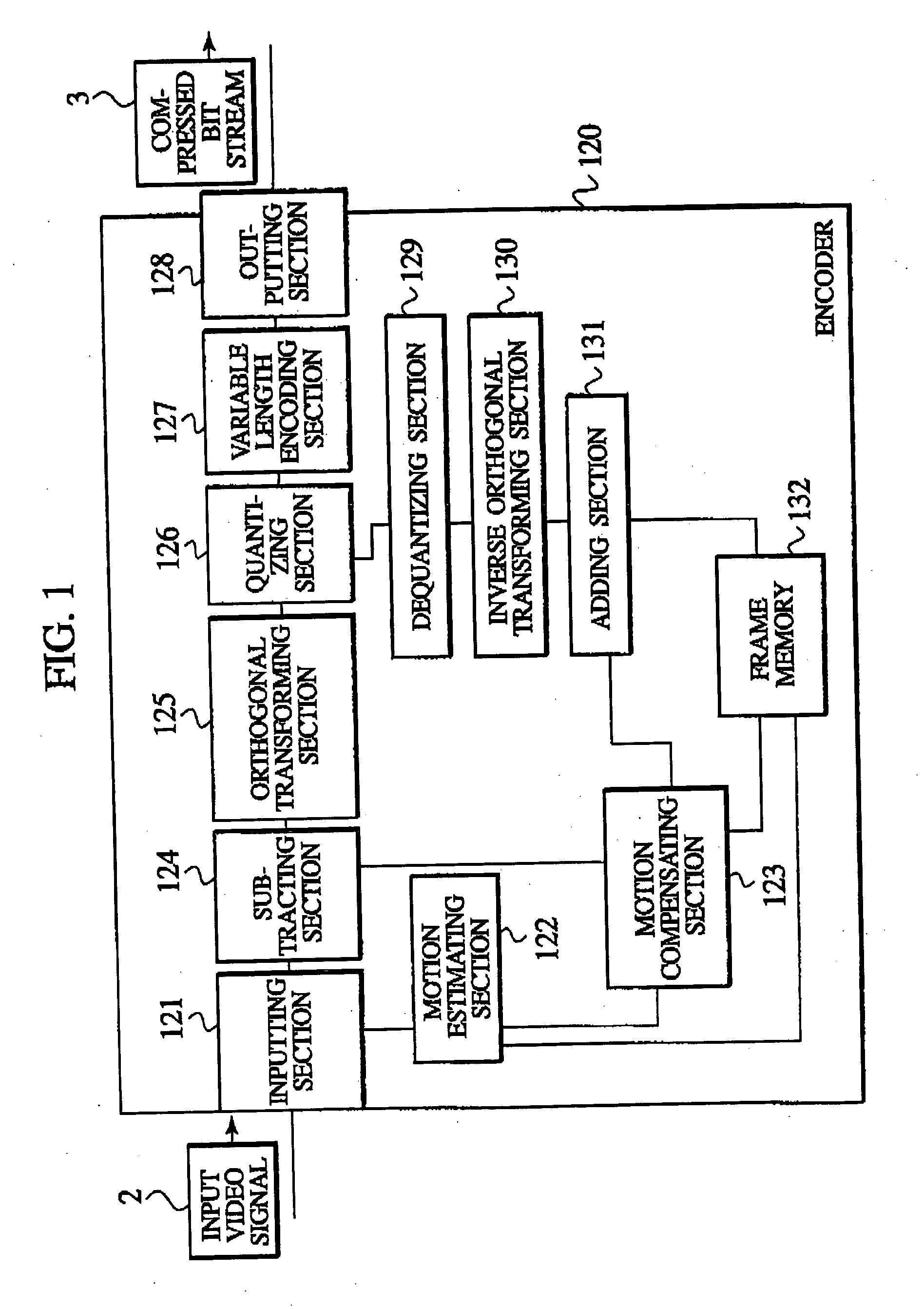
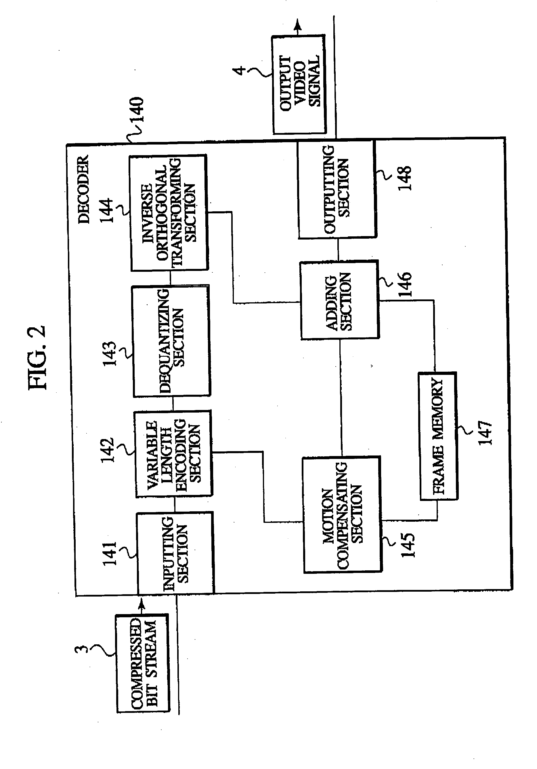
[0191] A description will be given of a video coding transmission system according to Embodiment 2 with reference to FIGS. 10 and 11. FIG. 10 is a block diagram showing an encoder 60 used in the video coding transmission system according to this embodiment. FIG. 11 is a block diagram showing a decoder 60 used in the video coding transmission system according to this embodiment.

[0192] The video coding transmission system according to this embodiment is compliant with the ITU-T H.26L coding system and has a configuration to which necessary modifications are added on that basis. The H.26L coding system is described in the ITU-T SG16 Q.6 VCEG-M81, "H.26 Test Model Long Term Number7 (TML-7) draft0," and the like.

[0193] Compared to the video coding transmission system according to the aforementioned Embodiment 1, the video coding transmission system according to this embodiment is modified in terms of miniaturization of the unit of "sub-blo...

embodiment 3

CONFIGURATION OF VIDEO CODING TRANSMISSION SYSTEM TO THE PRESENT INVENTION

[0262] A description will be given of a video coding transmission system according to Embodiment 3 of the present invention with reference to the drawings. Similar to the case of the Embodiment 2 of the present invention, the video coding transmission system according to this embodiment is compliant with the ITU-T H.26L coding system and provided with a configuration to which modifications necessary for carrying out this present invention are added on that basis. The configuration of the video coding transmission system according to this embodiment is shown in FIGS. 10 and 11 as well as the case of the Embodiment 2.

[0263] Compared to the video coding transmission system according to the Embodiment 2, the video coding transmission system according to this embodiment is modified in the following points.

[0264] First, the video coding transmission system according to this embodiment is modified in terms of settin...


PUM


Abstract

An object of the present invention is to allow portions which are subjected to a coding in inter-frame prediction mode and portions which are subjected to coding in intra-frame prediction mode to be mixed in one macro block without changing the framework of macro blocks. The present invention provides an encoder which encodes each of first image blocks of a video. The encoder includes prediction mode selection information generating means for generating prediction mode selection information which indicates that a first prediction mode for reducing temporal redundancy is applied to each of second image blocks or that a second prediction mode for reducing spatial redundancy is applied to each of the second image blocks. The second image blocks are obtained by dividing the first image blocks. The encoder includes predictive residual signal generating means for generating a predictive residual signal by applying the selected first or second prediction mode to each of the second image blocks. The encoder includes transmitting means for transmitting the prediction mode selection information in association with the predictive residual signal.

Description

[0001] The present invention relates to a video coding transmission system and a video coding transmission method, and relates to an encode, a decoder, an encoding method, a decoding method, and a program which are suitable for use in the same.[0002] A description will be given of examples of an encoder and a decoder used in a conventional video coding transmission system with reference to FIGS. 1 and 2. FIG. 1 is a block diagram showing a schematic configuration of the encoder used in the conventional video coding transmission system. FIG. 2 is a block diagram showing a schematic configuration of the decoder used in the conventional video coding transmission system.[0003] The encoder 120 shown in FIG. 1 and the decoder 140 shown in FIG. 2 are a digital video encoder and a digital video decoder, respectively, which are compliant with the H.263 coding system described in ITU-T Recommendation H.263 "Video coding for low bit rate communication".[0004] The encoder 120 reduces temporal r...

Claims


Application Information

Patent Timeline
Patent Type & Authority Applications(United States)
IPC IPC(8): G06T9/00H04N19/50H04N19/107H04N19/134H04N19/136H04N19/137H04N19/139H04N19/196H04N19/423H04N19/46H04N19/503H04N19/51H04N19/513H04N19/593H04N19/60H04N19/61H04N19/70H04N19/82H04N19/91
CPCH04N19/105H04N19/503H04N19/176H04N19/70H04N19/46H04N19/51H04N19/517H04N19/593H04N19/107H04N19/14H04N19/82H04N19/527H04N19/61
Inventor KOBAYASHI, MISURUKOBAYASHI, MINORUSEKIGUCHI, SHUNICHIYAMAGUCHI, HIROYUKIADACHI, SATORU
Owner NTT DOCOMO INC
Why Eureka
Try Eureka