Sonar imaging system for mounting to watercraft

a technology for imaging systems and watercraft, applied in the field of sonar imaging systems, can solve problems such as damage or loss of equipment, and achieve the effects of improving accuracy, reducing damage, and increasing coverage area

Active Publication Date: 2006-02-02
JOHNSON OUTDOORS
View PDF93 Cites 65 Cited by
  • Summary
  • Abstract
  • Description
  • Claims
  • Application Information

AI Technical Summary

Benefits of technology

[0007] The system of the present invention realizes several advantages over the traditional towfish side scan sonar systems. It is more convenient because there are no deployment requirements of getting the transducer towfish into the water, no cable handling hassles and tangles, no precise speed control requirements to keep the towfish at the right depth and prevent it from hitting the bottom, no complicated large diameter turn requirements to prevent the towfish from hitting the bottom when you want to turn the boat, and no worries about getting the lines and cable tangled when fishing. The system of the present invention can even used for imaging by a watercraft in reverse.
[0013] In a still further preferred embodiment, GPS imaging is also provided with the side imaging. In such embodiments a cursor mode allows a user to move the cursor over a target of interest on the screen image and set a waypoint for the location of the structure. The GPS history may be used to determine the distance back and the sonar may be used to determine the distance to the side. The GPS speed can be used to provide the screen scroll rate to provide more accurate front to back target dimensions. Without GPS or a speed sensor a fast scroll rate and a slow boat speed will elongate targets and a slow scroll rate and a fast boat speed will shorten targets. The corners of screen captures can be marked so that large area composite mosaic images can be generated in the unit or post processed later. Preferably, one view that shows both side imaging and navigation information is provided. This makes it easier to follow tracks and provide efficient area coverage.

Problems solved by technology

Most natural and especially man-made lakes have rocks, stumps and standing timber that can snag a towfish and cause damage or loss of the equipment.

Method used


Image

  • Sonar imaging system for mounting to watercraft
  • Sonar imaging system for mounting to watercraft
  • Sonar imaging system for mounting to watercraft

Examples


Embodiment Construction

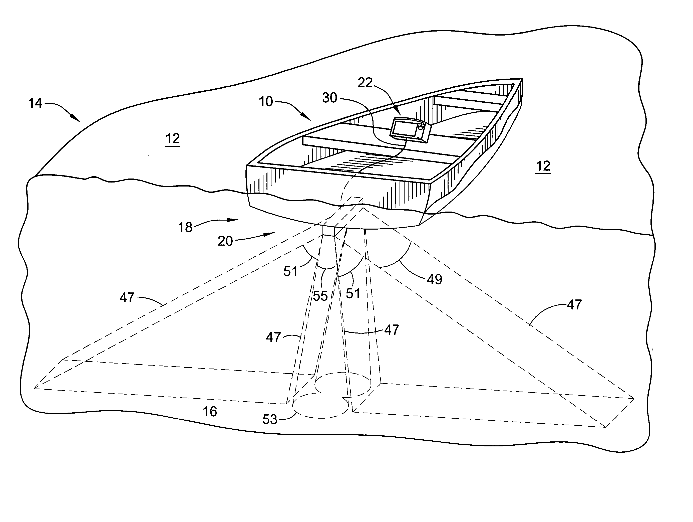
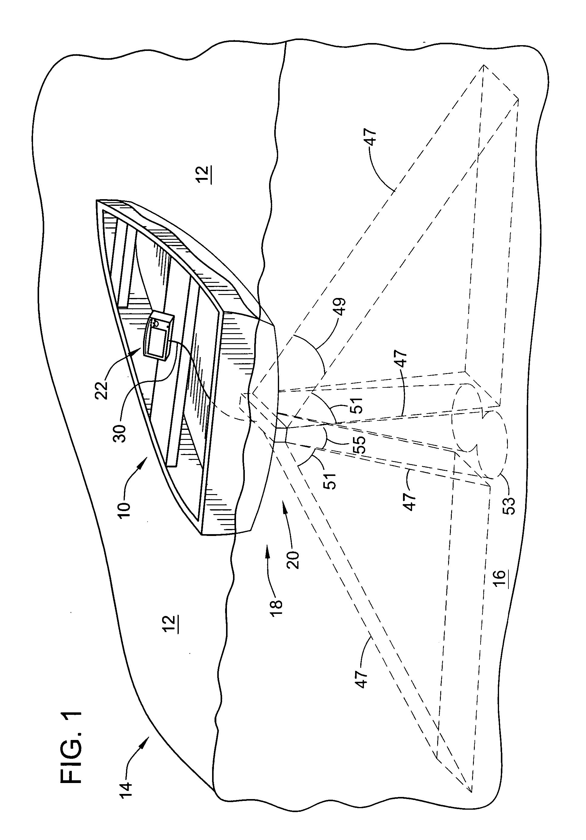
[0030] Turning now to the drawings, FIG. 1 illustrates a vessel (shown as a watercraft 10) on a surface 12 of a body of water 14 having a bottom 16. A sonar imaging system 18 is mounted or coupled to the watercraft 10 (e.g., rather than being towed by a flexible cable behind the watercraft 10) and is configured to scan the water below and to the sides of the watercraft (i.e., a boat mounted side scan sonar system). The sonar imaging system 18 comprises a transponder or transducer 20 coupled to an electronic control head unit 22 located at the watercraft 10. The sonar imaging system 18 repetitively scans the body of water 14 for fish and other underwater articles with transmissions of acoustic waves and receiving and displaying the sonar returns, with the duration of receiving being a function of the determined depth from a prior transmission.

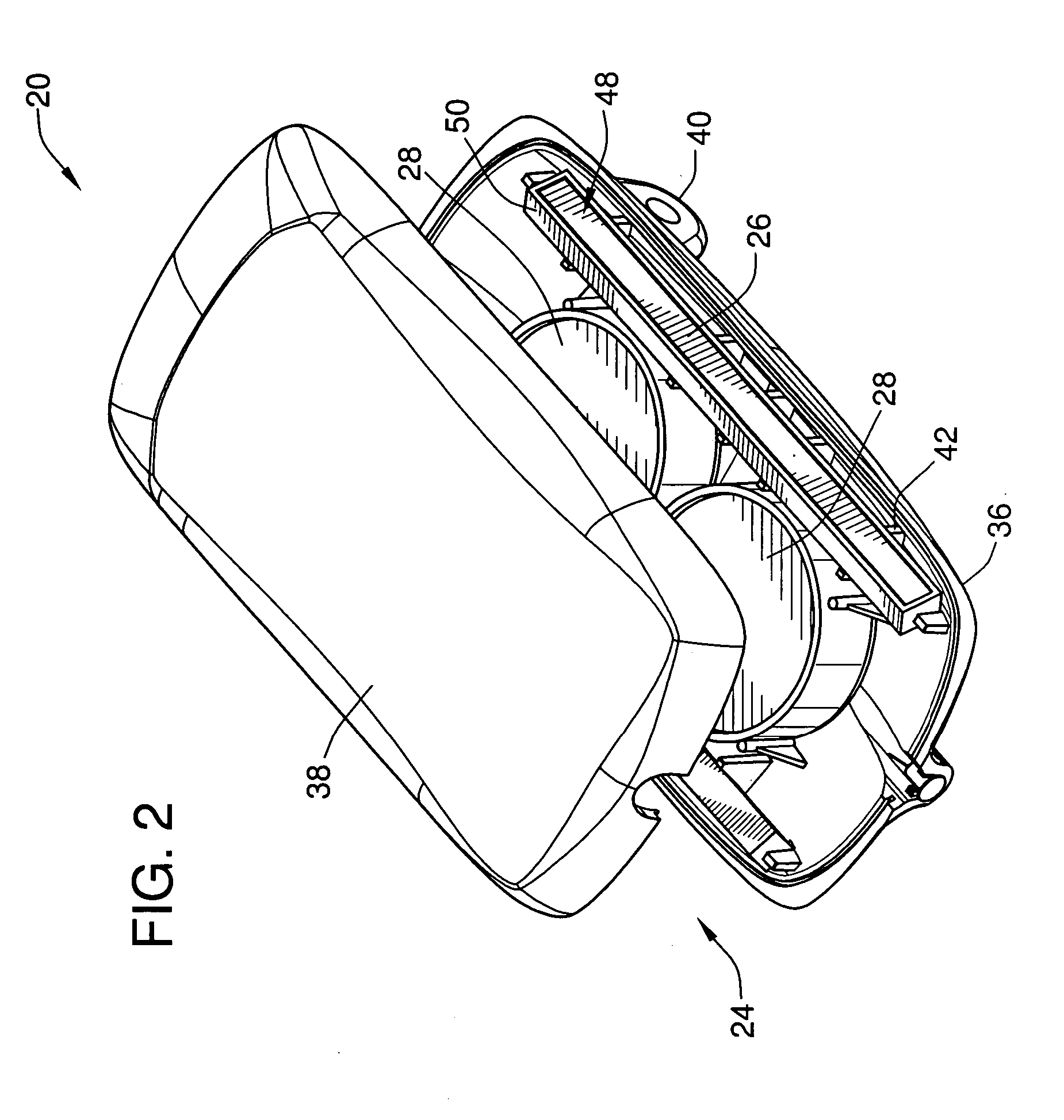
[0031] Referring to FIGS. 2-11, the transducer 20 includes a housing 24, a sonar array (in the form of a plurality of acoustic elements shown ...


PUM


Abstract

A sonar imaging system for a watercraft is disclosed. The sonar imaging system comprises a transducer coupled to the watercraft and having at least one side scanning element and at least one bottom scanning element, an electronic control head unit coupled to the transducer and configured to display sonar images. The downward acoustic elements may be circular and the side scan acoustic elements may be rectangular. A software filter may be provided to remove noise generated by a spark plug or other operation of a motor for the watercraft.

Description

CROSS-REFERENCE TO RELATED PATENT APPLICATIONS [0001] This patent application claims the benefit of U.S. Provisional Patent Application No. 60 / 598,326, filed Aug. 2, 2004, the teachings and disclosure of which are hereby incorporated in their entireties by reference thereto.FIELD OF THE INVENTION [0002] The present invention relates generally to sonar imaging systems for use in sport fishing applications such as in a fish finder, sonar depth sounder, etc., and more particularly to side scan sonar imaging systems for imaging of the underwater environment to the sides of the watercraft rather than just below the watercraft. BACKGROUND OF THE INVENTION [0003] Sonar devices that transmit sound waves have been used previously to obtain information about underwater articles, including fish, structures and obstructions, and the bottom. The sound waves travel from a transducer mounted to a bottom surface of the vessel through the water. The sound wave transmits from the sonar devices in div...

Claims


Application Information

Patent Timeline
Patent Type & Authority Applications(United States)
IPC IPC(8): G01S15/89G01S19/19
CPCG01S7/521G01S15/96G01S15/8902G01S15/107
Inventor BETTS, DAVID A.DERROW, ROBERT W.HOWELLS, DAVID J.
Owner JOHNSON OUTDOORS
Why Eureka
Try Eureka