Anastomotic leg arrangement

a leg arrangement and anastomosis technology, applied in the field of anastomosis leg arrangement, can solve the problems of time-consuming and/or difficult, requiring delicate motor control, and tearing of the vessel

Inactive Publication Date: 2006-02-02
BY PASS
View PDF0 Cites 51 Cited by
  • Summary
  • Abstract
  • Description
  • Claims
  • Application Information

AI Technical Summary

Benefits of technology

[0007] Optionally, the leg compacting system comprises a leg receptacle for each leg. Optionally, the receptacles prevent tangling of the legs during compacting and / or releasing of the legs. Optionally, the receptacles set relative leg positions for eversion.
[0014] An aspect of some embodiments of the invention relates to a noose controller. Optionally, the controller is stored in a configuration which elastically urges the noose to close. Optionally, a lock is provided to reduce stress on the noose itself. Optionally, the noose is cut at a certain position of the controller.
[0018] An aspect of some embodiments of the invention relates to a step-action delivery system in which the delivery system advances and retracts a connector, in addition to or instead of at least some such motions by a user. In an exemplary embodiment of the invention, the delivery system separately provides the actions of advancing the connector tip relative to the delivery system and tearing of the connector, in which no further advancing is provided. Optionally, a user can deploy an anastomosis connector without being required to move the delivery system once the legs are inserted into an aperture in the blood vessel. In an exemplary embodiment of the invention, the forces required to tear the connector are provided by releasing a spring, rather than by the user. Optionally, a single control is used for both steps.
[0020] An aspect of some embodiments of the invention relates to using a shunt during anastomosis. In an exemplary embodiment of the invention, a shunt is inserted into a target vessel through an aperture formed therein for an anastomosis. The shunt prevent blood from flowing near the aperture and shunts it around the anastomosis location so that tissue served by the blood vessel is not starved. Optionally, the shunt serves to stretch out the blood vessel, so the aperture is not collapsed and is easily accessible. In an exemplary embodiment of the invention, the shunt is removed between legs of the connector, once the connector is properly placed.
[0038] In an exemplary embodiment of the invention, said wire comprises a side wall adapted to prevent legs from slipping away from compacting.

Problems solved by technology

The manipulation of the vessel to be everted may require delicate motor control by the physician and there is a risk of tearing of the vessel due to its being stretched.
Such exact insertion may also require delicate motor control and be time consuming and / or difficult.

Method used


Image

  • Anastomotic leg arrangement
  • Anastomotic leg arrangement
  • Anastomotic leg arrangement

Examples


Embodiment Construction

Leg Configuration for Eversion

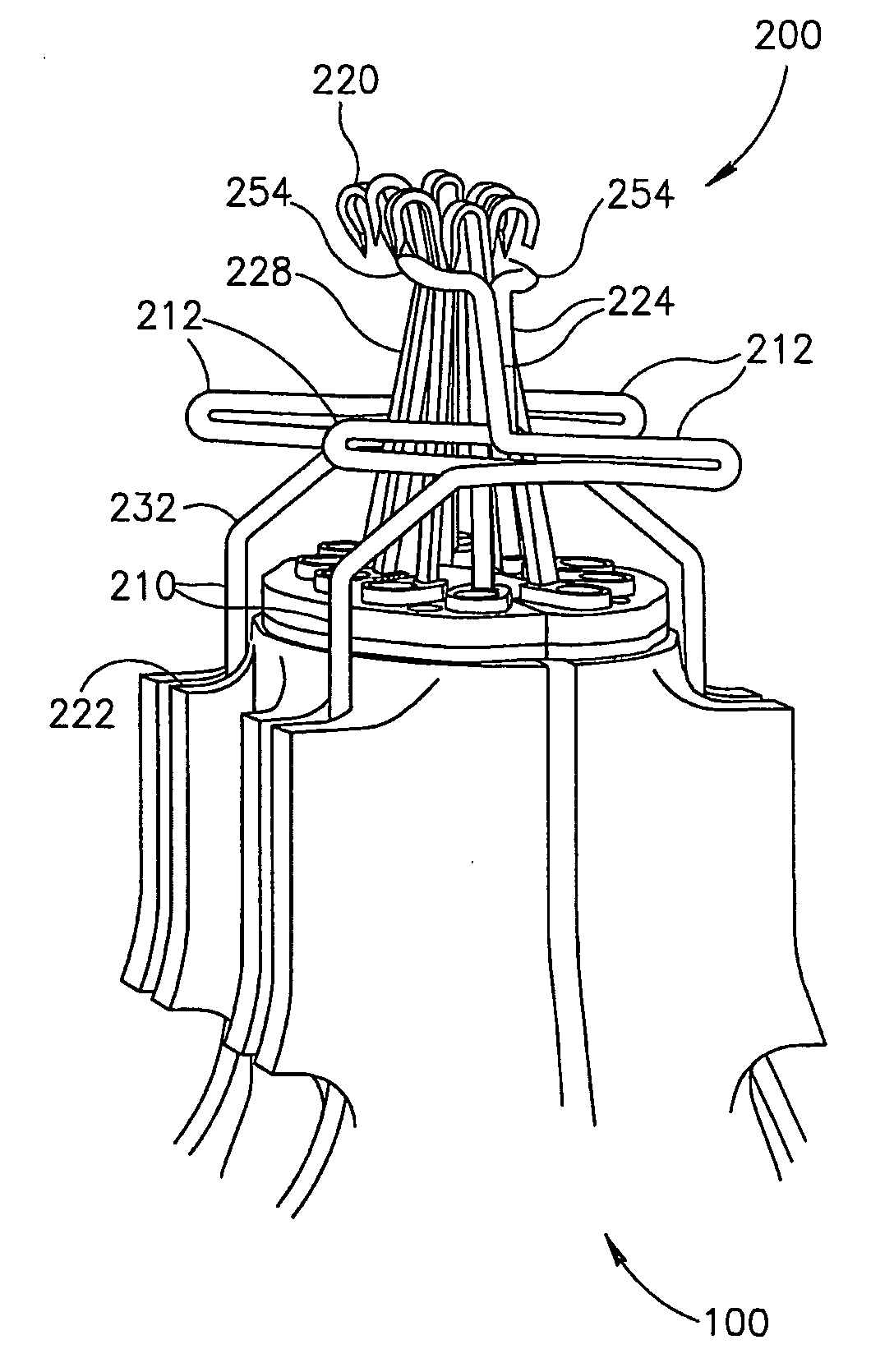
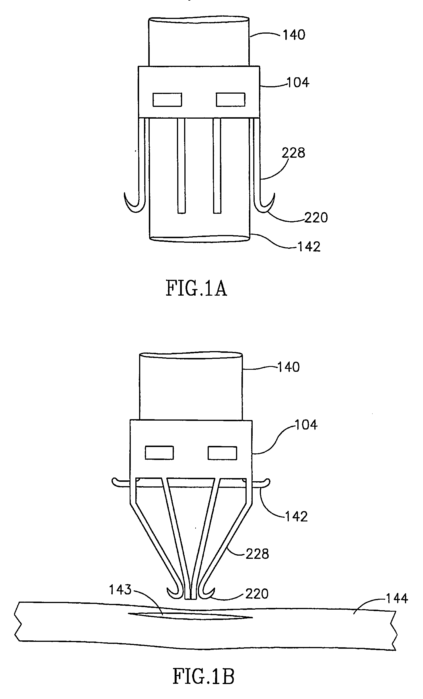
[0145]FIG. 1A shows a graft 140 being mounted on a part of an anastomotic connector 104. For clarity, the rest of the connector and / or other parts thereof and / or a delivery or holding system are not shown. To complete the mounting, a lip 142 of graft 140 needs to be everted over hooks 220 of forward legs 228. In the configuration shown, this requires stretching lip 142. In exemplary embodiments of the invention, as shown below, a leg compacting device is provided to radially compact legs 228, thereby reducing their outer radius and obviating or reducing the need to stretch lip 142.

[0146] In some embodiments of the invention, the leg compacting device also sets relative leg positions for eversion.

Leg Configuration for Insertion

[0147]FIG. 1B shows connector 104 being deployed, after a graft 140 is mounted thereon. In the type of anastomotic connection shown, hook ends 220 of legs 228 need to be inserted into an incision (or aperture) 143 in a target...


PUM


Abstract

A leg compacting system for compacting inwards a group of legs (228) of an anastomotic connector towards a central location thereof, comprising, a coupler for coupling to a delivery system on which said connector is mounted; and a plurality of leg confiners (820), said leg confiners (820) configured to selectively move in an inwards direction and said confiners configured to have a resting compacted configuration in which a space of between 7 and 1 mm in width is maintained between the innermost leg contacting sections of said confiners such that a graft vessel suitable for mounting on said connector can be passed between said confiners (820).

Description

RELATED APPLICATIONS [0001] The present application claims priority from and is a continuation-in-part of PCT application PCT / IL02 / 00790, filed on Sep. 25, 2002, which designates the US, now published in English as WO 03 / 026475. It also claims priority as well as the benefit under 119 (e) of U.S. Ser. No. 60 / 426,013, filed on Nov. 14, 2002. The disclosure of both applications is incorporated herein by reference.FIELD OF THE INVENTION [0002] The present invention relates to systems and tools used in conjunction with anastomotic connectors and / or manipulation of blood vessels. BACKGROUND OF THE INVENTION [0003] Connecting together of two blood vessels may be performed using an anastomotic connector. In an end-to-side connection, such a connector typically has a final diameter similar to that of the “end” vessel. In some connectors, the end vessel is everted over the connector. An example of such a connector is shown in Kaster U.S. Pat. No. 5,234,447, the disclosure of which is incorpo...

Claims


Application Information

Patent Timeline
Patent Type & Authority Applications(United States)
IPC IPC(8): A61B17/08A61BA61B17/00A61B17/11
CPCA61B17/00491A61B17/0644A61B17/11A61B2017/1135A61B2017/1103A61B2017/1107A61B17/115
Inventor LOSHAKOVE, AMIRNATIV, OFERKILEMNIK, IDOHEFER, GIL
Owner BY PASS
Why Eureka
Try Eureka