Footer track with moisture vent

a footer track and moisture vent technology, applied in the field of building construction, can solve the problems of ineffective removal of a sufficient amount of moisture from the track, the interior of the footer track, and the failure of prior art wall footer tracks to accommodate drainage or venting of moistur

Inactive Publication Date: 2006-02-09
SUTTON ADAM F
View PDF28 Cites 17 Cited by
  • Summary
  • Abstract
  • Description
  • Claims
  • Application Information

AI Technical Summary

Benefits of technology

[0007] Accordingly, a need exists for a footer track structure that effectively permits the evacuation of moisture from the interior of the footer track. Preferred embodiments of the present wall footer track are provided with a plurality of moisture vents, or drain openings configured to permit moisture within the stud space of an associated wall to readily escape. Desirably, a boundary of each drain opening is defined by both of a web of the footer track and one of the legs of the footer track. Advantageously, with such an arrangement, moisture within the stud space may be substantially or completely evacuated from the interior of the footer track. The drain openings may be of any shape and may be oriented in a parallel or alternating fashion along opposing sides of the footer track.

Problems solved by technology

In general, prior art wall footer tracks have failed to accommodated drainage or venting of moisture that has become trapped within the interior of the footer track, either during the construction process or within the space between the studs of the wall after completion of the building structure.
Without a sufficient drainage or ventilation mechanism, the prior art walls are susceptible to moisture buildup within the stud space, which may cause a variety of problems, such as damage to the wall covering elements (e.g., drywall) or facilitating mold growth, among others.
However, in practice, this arrangement has not proven effective at removing a sufficient amount of moisture from the track.

Method used


Image

  • Footer track with moisture vent
  • Footer track with moisture vent
  • Footer track with moisture vent

Examples


Embodiment Construction

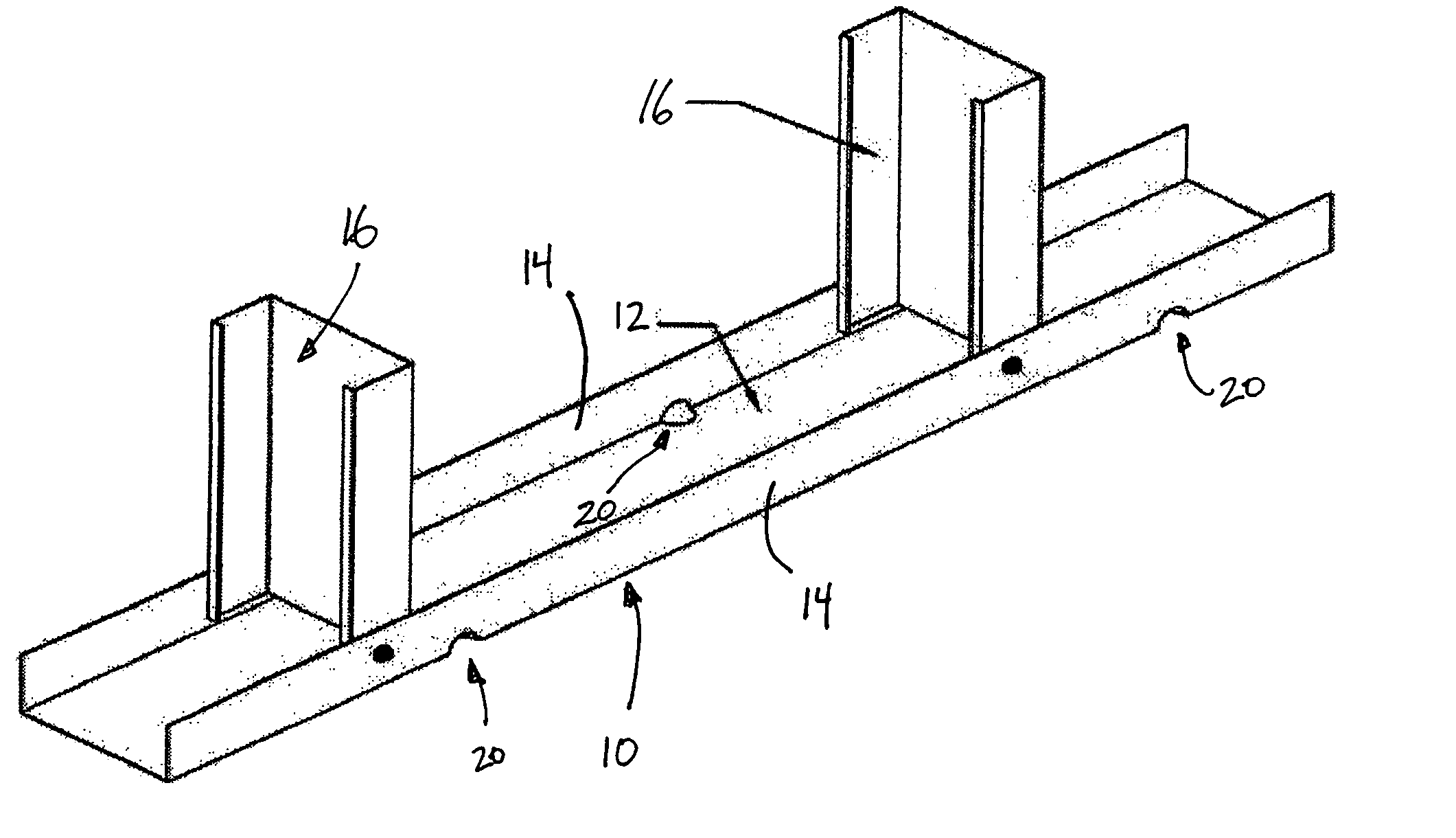
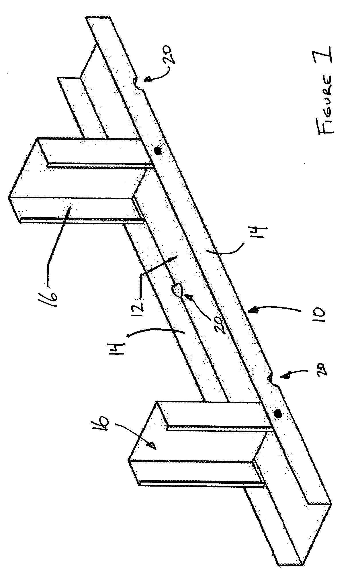
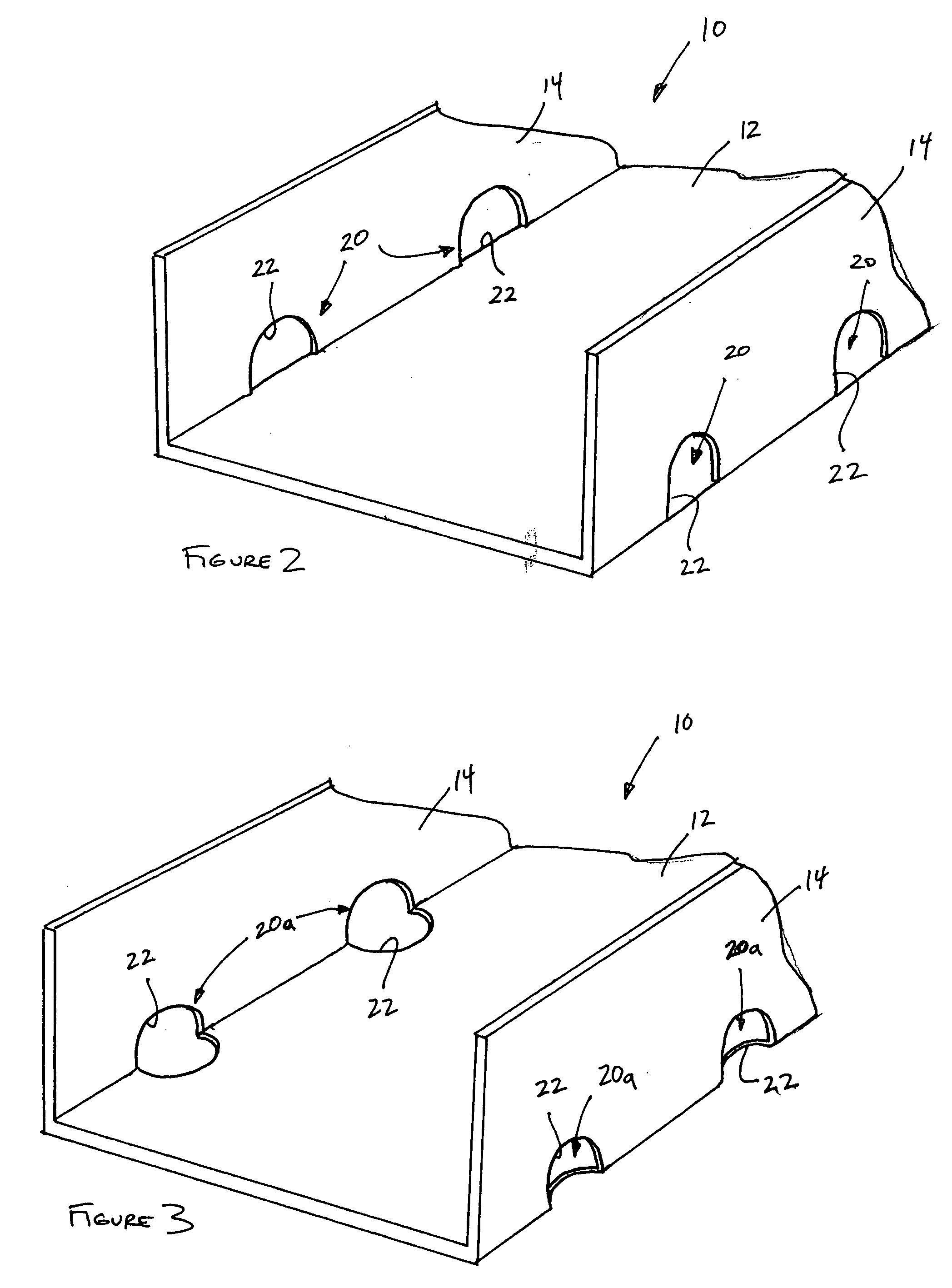
[0019]FIG. 1 illustrates a wall assembly including a footer track 10 having certain features, aspects and advantages of the present invention. Preferably, the footer track 10 includes a web 12 and a pair of legs 14 extending from opposing sides of the web 12. In the illustrated arrangement, the footer track 10 is generally C-shaped in cross-section. However, the footer track 10 may also be of other configurations as well. For example, in certain arrangements, the legs 14 may not extend from the web 12 in a generally perpendicular orientation, but may be oriented at other angles relative to the web 12. Further, in certain arrangements, the footer track 10 may include a portion defining a plurality of slots configured to locate and space studs 16 from one another. In such an arrangement, the footer track 10 may be generally M-shaped and include a central portion that defines the plurality of slots.

[0020] Preferably, the footer track 10 is configured to be placed with the web 12 resti...


PUM


Abstract

A footer track for supporting a plurality of wall studs, and a method for making a footer track, including a web and a pair of legs extending from opposing sides of the web. The pair of legs are spaced from one another a distance sufficient to accommodate a wall stud therebetween. The footer track defines a plurality of drain openings spaced along a length of the footer track. Preferably, each of the plurality of drain openings has a boundary defined by both of the web and one of the pairs of legs. In one arrangement, each drain opening extends a distance into the web such that the opening, itself, is defined by both the web and leg.

Description

RELATED APPLICATIONS [0001] This application claims priority to U.S. Provisional Application No. 60 / 668,661, filed Apr. 6, 2005, U.S. Provisional Application No. 60 / 629,566, filed Nov. 19, 2004 and U.S. Provisional Application No. 60 / 628,880, filed Nov. 18, 2004, the entireties of which are incorporated by reference herein and made a part of this specification.BACKGROUND OF THE INVENTION [0002] 1. Field of the Invention [0003] The present invention generally relates to building construction and, more specifically, relates to a wall footer track configured to permit drainage or venting of moisture within the stud space of a wall. [0004] 2. Description of the Related Art [0005] In general, prior art wall footer tracks have failed to accommodated drainage or venting of moisture that has become trapped within the interior of the footer track, either during the construction process or within the space between the studs of the wall after completion of the building structure. Without a suf...

Claims


Application Information

Patent Timeline
Patent Type & Authority Applications(United States)
IPC IPC(8): E02D19/00
CPCE04B2/7457E04F17/00E04B2/789
Inventor SUTTON, ADAM F.
Owner SUTTON ADAM F
Why Eureka
Try Eureka