Explosive bolt

a technology of explosion bolts and bolts, which is applied in the direction of threaded fasteners, launching weapons, screwdrivers, etc., can solve the problems of explosion bolts that cannot be used, cannot be anticipated, and have the device malfunction, so as to minimize the explosion impact and noise, improve productivity and reliability, and minimize the amount of gunpowder used

Inactive Publication Date: 2006-02-09
AGENCY FOR DEFENSE DEV
View PDF7 Cites 19 Cited by
  • Summary
  • Abstract
  • Description
  • Claims
  • Application Information

AI Technical Summary

Benefits of technology

[0013] Therefore, an object of the present invention is to provide an explosive bolt capable of minimizing explosion impact and noise and improving productivity and reliability by minimizing the amount of gunpowder used and by freely designing and fixing a position of a cut portion.

Problems solved by technology

However, such a conventional explosion bolt has following problems.
First, noise and impact generated in explosion may disturb electronic devices or sensitive sensors near the explosion, generate cracks on a liquid carrying pipe or cause mal-functioning of the device.
Secondly, because cutting is made at a random position, it is impossible to anticipate a cut position and the cut position cannot be freely controlled.
Because of such difficulties, an accident may occur due to undesired explosion, and a cut surface of the bolt body cannot be freely modified and designed.
Thirdly, the ignition means is not easily assembled and is not suitable to employ in a bolt which is small or has a complex shape.
Accordingly, a manufacturing process becomes complex, and its manufacturing cost is increased.
Such problems more severely occur as the amount of gunpowder used is increased.
Namely, if the amount of gunpowder being used is increased, noise and impact also increase, and it becomes more difficult to anticipate a cut position.

Method used


Image

  • Explosive bolt
  • Explosive bolt
  • Explosive bolt

Examples


Embodiment Construction

[0024] Reference will now be made in detail to the preferred embodiments of the present invention, examples of which are illustrated in the accompanying drawings.

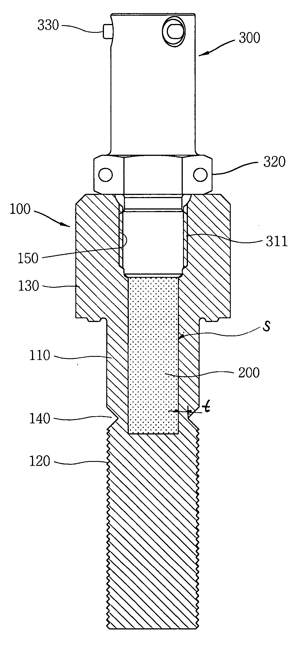
[0025]FIG. 3 is a sectional view showing a first embodiment of an explosion bolt in accordance with the present invention.

[0026] As shown, the explosion bolt in accordance with the present invention includes a bolt body 100 forming a receiving space (S) therein; a pressure transmitting means 200, an uncompressible material received in the receiving space (S) of the bolt body 100; a pressure generating means 300 coupled to the bolt body 100, generating pressure and transmitting the pressure to the pressure transmitting means 200; and a cut portion 140 formed at the bolt body 100 and cut upon receiving the pressure.

[0027] The bolt body 100 includes a body portion 110; a screw portion 12 formed at one end of the body portion 110; and a head portion 130 formed at the other of the body portion 110. Preferably, SUS304 or SUS63...


PUM


Abstract

An explosive bolt includes: a bolt body forming a receiving space therein; a pressure transmitting means received in the receiving space of the bolt body; a pressure generating means connected to the pressure transmitting means and generating pressure; and a cut portion formed at the bolt body and cut upon receiving pressure generated from the pressure generating means through the pressure transmitting means. Accordingly, the amount of gunpowder used is minimized, and a position of a cut portion can be freely designed and fixed, thereby not only minimizing explosion impact and noise but also improving productivity and reliability.

Description

BACKGROUND OF THE INVENTION [0001] 1. Field of the Invention [0002] The present invention relates to an explosive bolt, and particularly, to an explosive bolt transmitting pressure generated in explosion to a cut portion and cutting the cut portion. [0003] 2. Description of the Background Art [0004] A means for cutting coupled two parts is being commonly used in fields related to multi-stage rockets, rocket boosters, space missiles and commercial vehicles. Currently, an explosive bolt is a representative cutting means for immediately separating coupled two parts into two parts or more, and this is disclosed in Korean Patent Application Publication Nos. 1994-04227, 2000-09634 and the like. [0005]FIGS. 1 and 2 shows conventional explosive bolts. [0006] As shown in FIG. 1, an ignition device 2 installed inside a bolt body 1 coupling two parts is operated by receiving an electric signal through a lead line 2, and separation gunpowder 3 filled in the bolt body 1 is exploded by such opera...

Claims


Application Information

Patent Timeline
Patent Type & Authority Applications(United States)
IPC IPC(8): B64D1/04
CPCF42B3/006F16B31/005F16B35/00F16B35/04
Inventor LEE, YEUNG-JOCHOI, CHANG-SUNKIM, DONG-JIN
Owner AGENCY FOR DEFENSE DEV
Why Eureka
Try Eureka