Fuel cell vehicle architecture

a fuel cell and vehicle technology, applied in the direction of electrochemical generators, electric propulsion mounting, transportation items, etc., can solve the problems of limited packing space between the rear wheels, limit the vehicle travel range between refuelings, etc., to achieve the effect of increasing the fuel cell stack size, and reducing the size of the fuel tank

Inactive Publication Date: 2006-02-09
GM GLOBAL TECH OPERATIONS LLC
View PDF9 Cites 47 Cited by
  • Summary
  • Abstract
  • Description
  • Claims
  • Application Information

AI Technical Summary

Benefits of technology

[0007] According to a second aspect of the invention, a fuel cell vehicle is provided with design flexibility whereby a decrease in fuel tank size enables an increase in fuel cell stack size. The fuel cell stack is located adjacent to the fuel tank, and is oriented such that additional fuel cells may be added on the side of the stack that faces the tanks. Accordingly, when a long tank is removed and replaced with a shorter tank, the fuel cell stack can be enlarged by adding fuel cells which occupy space formerly occupied by the large tank. The design also accommodates vehicle manufacturers, who can assemble a plurality of vehicles having a common chassis and frame design, but having different fuel cell and tank configurations.

Problems solved by technology

However, packaging space between the rear wheels is limited, which, in turn, limits the size of the tanks and the vehicle travel range between refuelings.

Method used


Image

  • Fuel cell vehicle architecture
  • Fuel cell vehicle architecture
  • Fuel cell vehicle architecture

Examples


Embodiment Construction

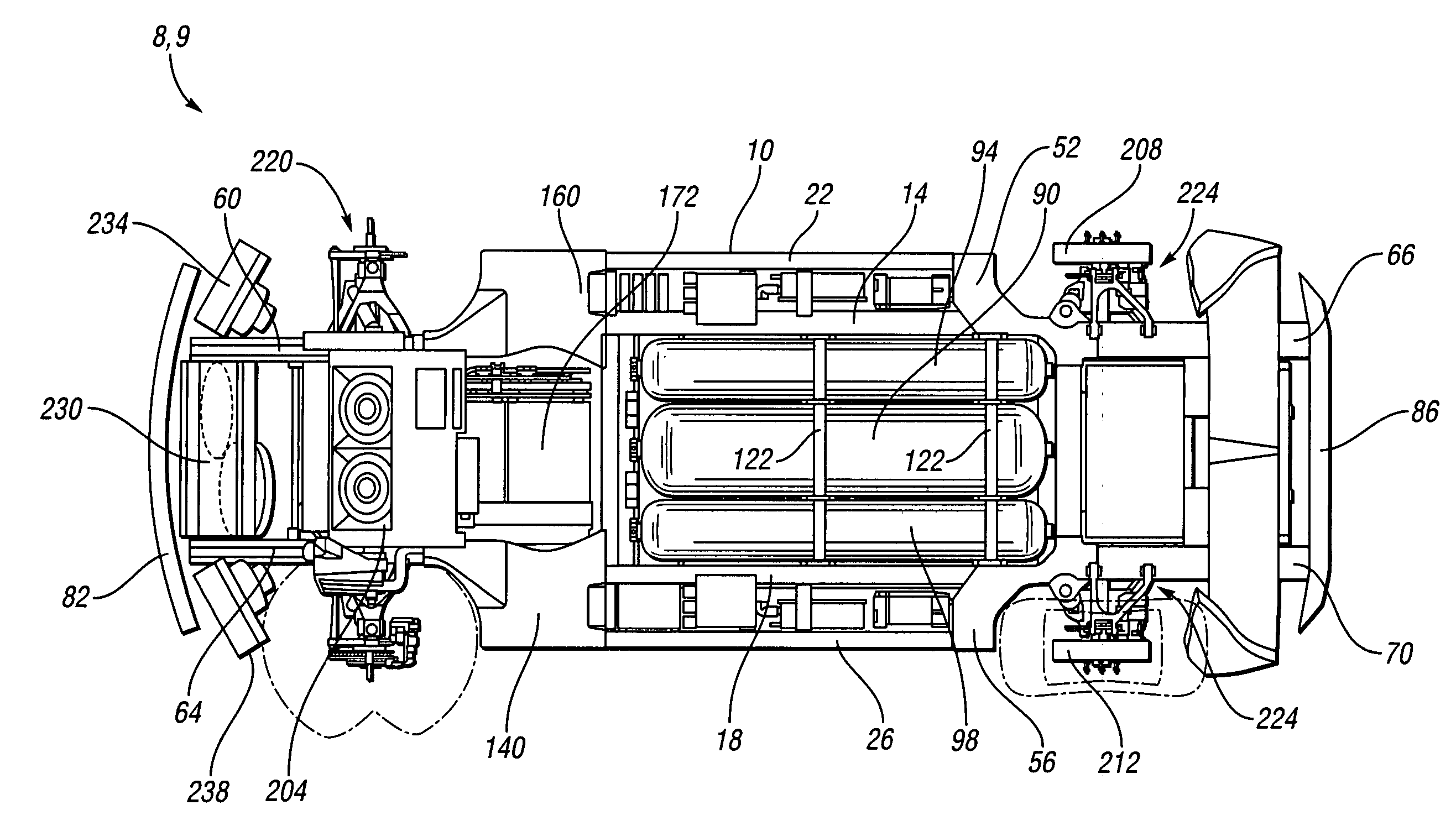
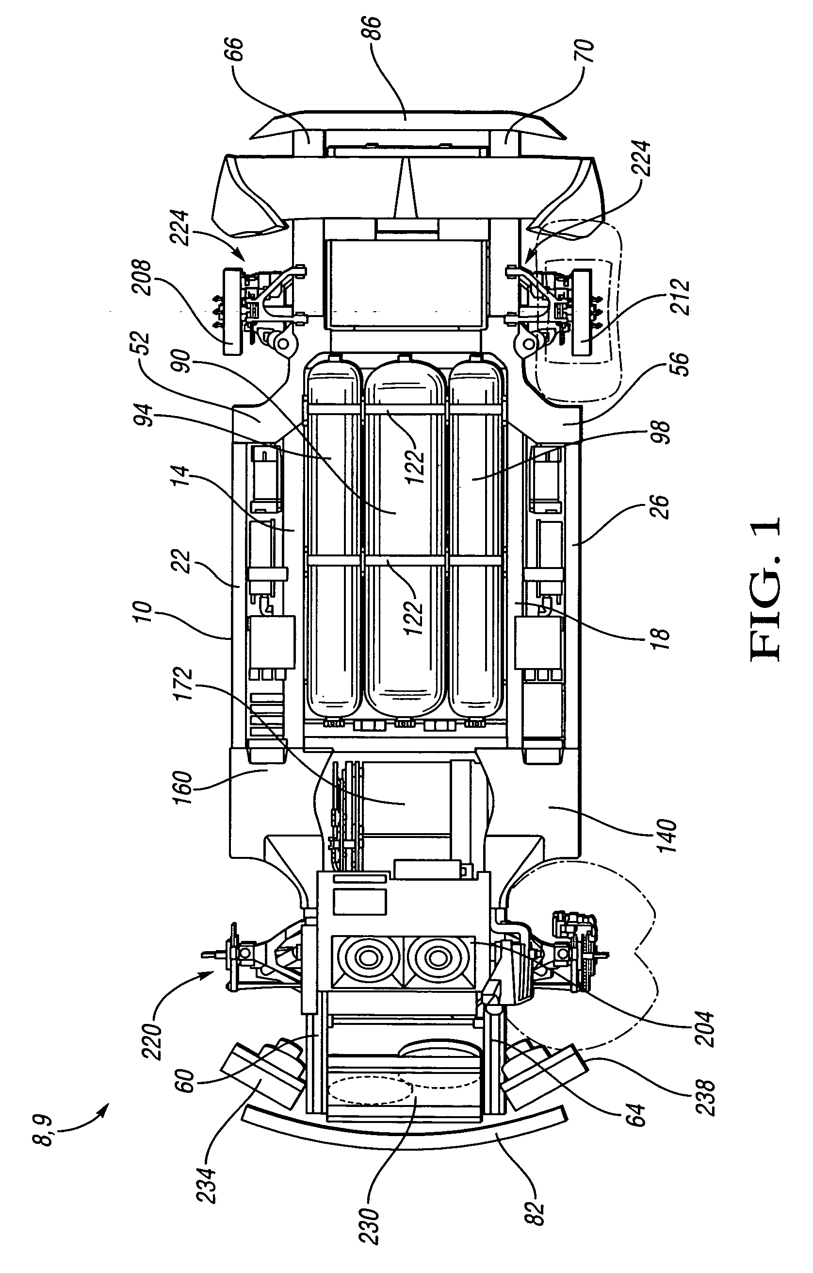
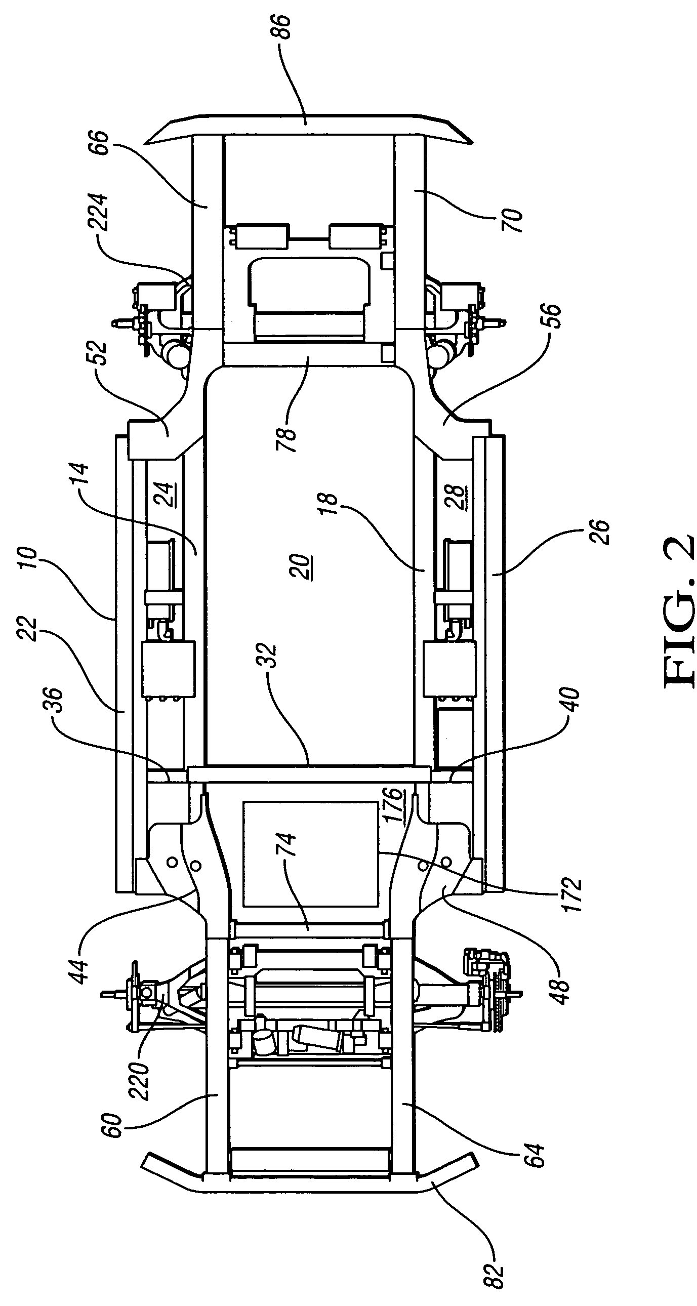
[0015] Referring to FIG. 1, a chassis 8 for a vehicle 9 is schematically depicted. The chassis includes a structural frame 10. Referring to FIGS. 2 and 3, the frame includes a first rail 14 and a second rail 18 cooperating to at least partially define a protected cavity 20 therebetween. A third rail 22 is outboard of the first rail 14 and cooperates with the first rail 14 to at least partially define a first lateral cavity 24 outboard of the protected cavity 20. A fourth rail 26 is outboard of the second rail 18 and cooperates with the second rail 18 to at least partially define a second lateral cavity 28 outboard of the protected cavity 20. Various chassis components are shown inside the lateral cavities 24, 28. Cross member 32 rigidly interconnects the first and second rails 14, 18. Cross member 36 rigidly interconnects the first and third rails 14, 22. Cross member 40 rigidly interconnects the second and fourth rails 18, 26.

[0016] The frame 10 also includes a first node 44, a se...


PUM


Abstract

A vehicle chassis includes a frame defining a cavity, and a tank configured to store compressed hydrogen gas. The tank is at least partially located within the cavity, and is longitudinally oriented with respect to the frame to maximize the fuel-storage capability of the vehicle chassis. In an exemplary embodiment, a floorpan includes a concavity to accommodate at least a portion of the tank, with a corresponding protuberance in the passenger compartment floor surface of the vehicle chassis.

Description

CROSS REFERENCE TO RELATED APPLICATIONS [0001] This application is a continuation in part of U.S. patent application Ser. No. 10 / 202,396, filed Jul. 24, 2002, which claims the benefit of U.S. Provisional Application 60 / 314,501, filed Aug. 23, 2001, and U.S. Provisional Application 60 / 337,994, filed Dec. 7, 2001; this application also claims the benefit of U.S. Provisional Patent Application No. 60 / 608,585, filed Sep. 10, 2004; each of the aforementioned applications is hereby incorporated by reference in its entirety.TECHNICAL FIELD [0002] This invention relates to vehicle chassis and powertrains having longitudinally-oriented compressed-gas storage tanks beneath a passenger compartment. BACKGROUND OF THE INVENTION [0003] Prior art vehicles typically include an internal combustion engine that is contained in an engine compartment in the front or rear of the vehicle body. The engine is fueled by a liquid, such as gasoline or diesel fuel, which is typically stored in a tank toward the...

Claims


Application Information

Patent Timeline
Patent Type & Authority Applications(United States)
IPC IPC(8): B60P3/22
CPCB60K1/04B60K15/063B60K15/07B62D21/16Y02E60/321H01M8/04208H01M2250/20Y02T90/32Y02E60/50F17C2270/0184Y02E60/32Y02T90/40
Inventor BORRONI-BIRD, CHRISTOPHER E.SHABANA, MOHSEN D.
Owner GM GLOBAL TECH OPERATIONS LLC
Why Eureka
Try Eureka