
Vehicle roll stabilizing damper system

a technology of rolling damper and suspension system, which is applied in the direction of resilient suspension, interconnection system, vehicle components, etc., can solve the problems of limiting the tuning of roll damping into the primary suspension system, providing minimal roll resistance or “damping, and not providing adequate roll resistance or damping

Inactive Publication Date: 2006-02-09
ILLINOIS TOOL WORKS INC
View PDF17 Cites 28 Cited by
  • Summary
  • Abstract
  • Description
  • Claims
  • Application Information

AI Technical Summary

Benefits of technology

[0013] An advantage of the present invention is providing a vehicle body roll damping system that can work together with but is adjustable independently of a vehicle primary suspension system and a roll stabilizer system allowing tuning of the primary suspension system for driving comfort and independent tuning of the roll damping system for damping performance.
[0014] Another advantage of the present invention is providing a vehicle body roll damping system that can be integral with the roll stabilizer system.
[0015] Still another advantage of the present invention is providing a vehicle body roll damping system that can be independent of the roll stabilizer system.
[0016] A further advantage of the present invention is providing a vehicle body roll damping system that can be installed in conjunction with both single and dual compensator stabilizing systems.
[0017] A yet a further object of the present invention is providing a vehicle body roll damping system that can be installed with roll stabilizer bar systems.
[0018] Yet another advantage of the present invention is providing a vehicle body roll damper system that can be installed in advantageous locations above or below the lower control arms.

Problems solved by technology

While stabilizer systems as described operate effectively to return the vehicle to a neutral condition after vehicle body roll has been experienced, known systems provide minimal roll resistance or “damping” to inhibit the initial entry of the vehicle body into a roll condition.
However, tuning roll damping into the primary suspension systems is limited by the suspension dampers primary functions and the suspension geometry.
To provide adequate roll resistance or damping may not be acceptable with known suspension system tuning, as the reduction in ride comfort is too severe.

Method used


Image

  • Vehicle roll stabilizing damper system
  • Vehicle roll stabilizing damper system
  • Vehicle roll stabilizing damper system

Examples


Embodiment Construction

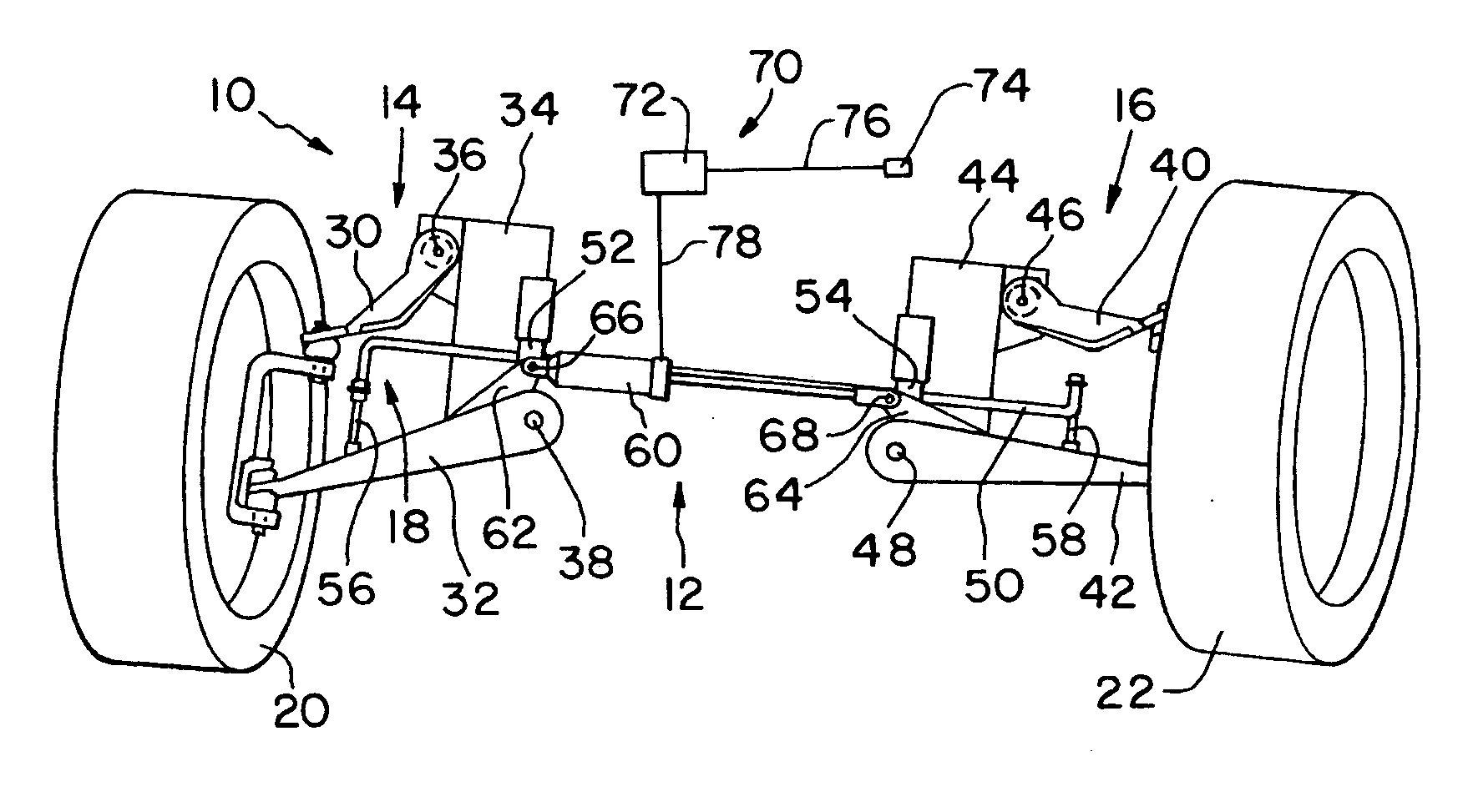
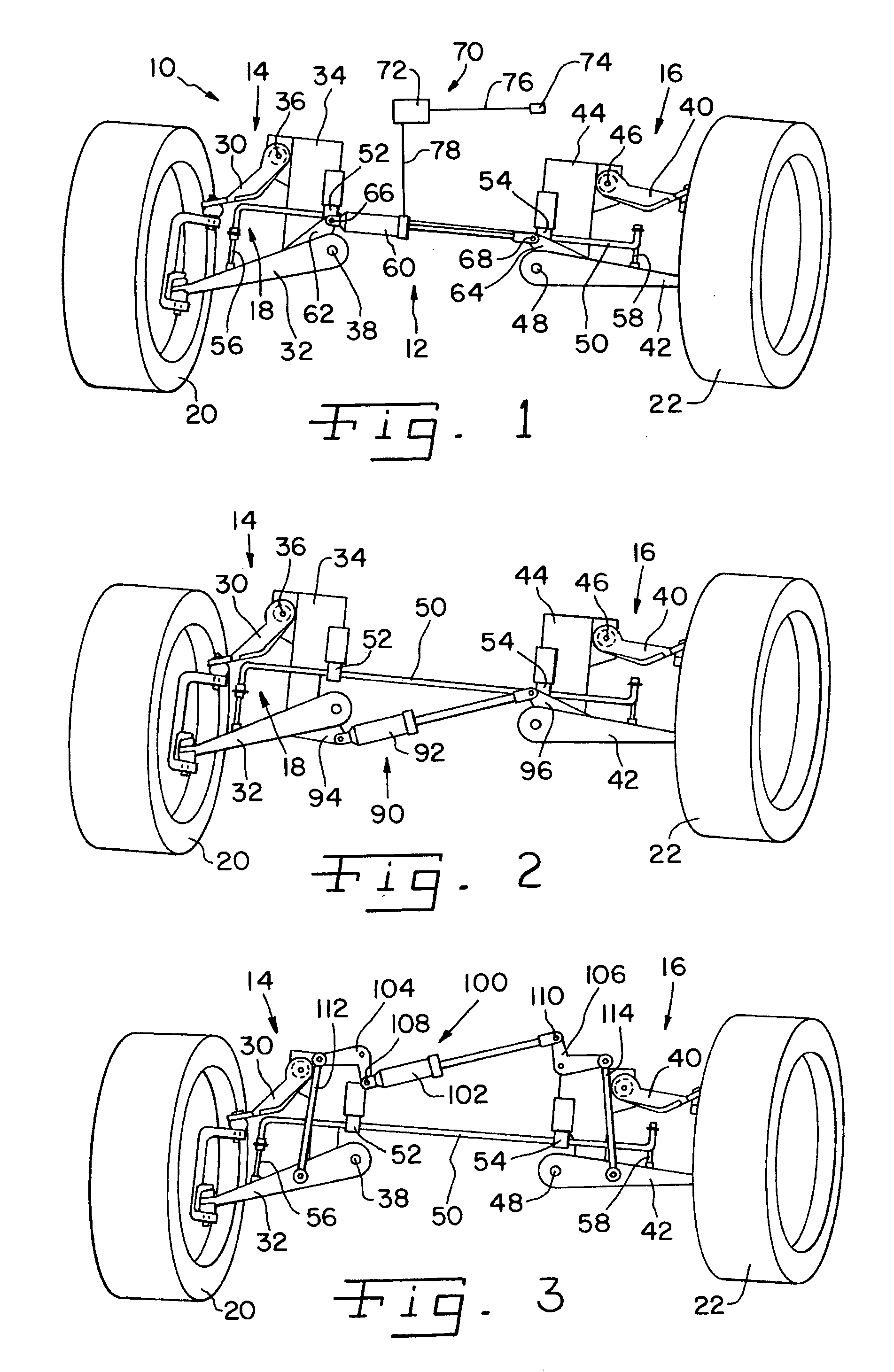
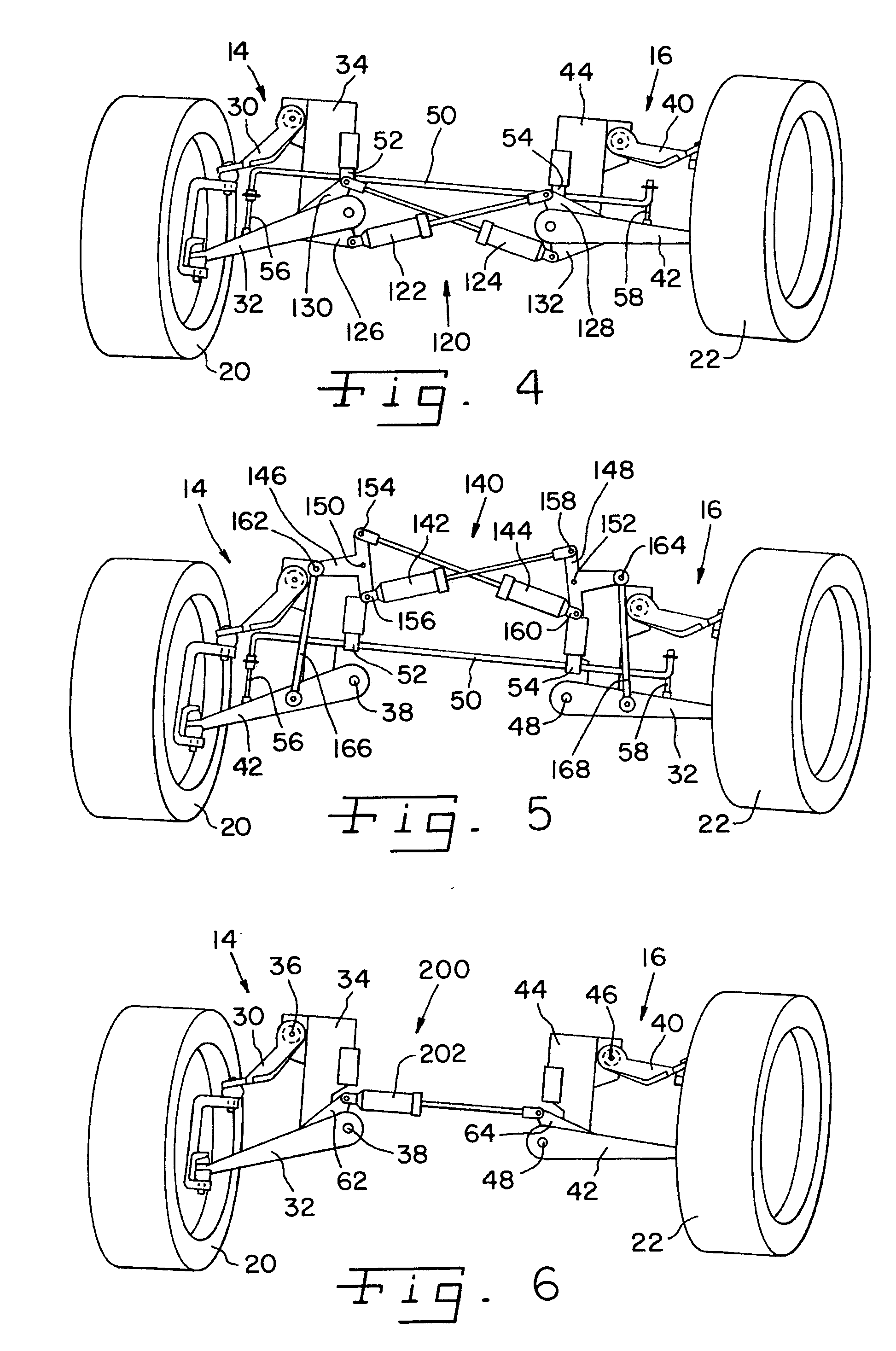
[0044] Referring now more specifically to the drawings and to FIG. 1 in particular, numeral 10 designates a front wheel assembly of a motor vehicle having a roll damping system 12 in accordance with the present invention. Front wheel assembly 10 further includes first and second primary suspension systems 14 and 16 and a torsional roll stabilizer system 18 for controlling the movements of wheels 20 and 22.

[0045] Primary suspension system 14 includes an upper control arm 30 and a lower control arm 32 each interconnected with a frame member 34 about pivotal connections 36 and 38, respectively. The manner in which upper and lower control arms 30 and 32, frame 34, pivotal connections 36, 38 and wheel 20 are interrelated one with another are conventional and well-understood by those skilled in the art. Accordingly, further explanation thereof will not be provided herein. Similarly, primary suspension system 16 includes an upper control arm 40 and a lower control arm 42 each interconnect...


PUM


Abstract

A damper system is connected between pivotal components of a vehicle suspension system to inhibit movement of the components during a condition of potential vehicle roll. The system can be actively or passively controlled. The damper system can have a single damper or multiple dampers and may be connected to work in conjunction with vehicle stabilizers including torsion bars, single compensator stabilizing systems and dual compensator stabilizing systems. In the compensator stabilizing systems, the damper can be separate from the compensators or integral with the compensators. The dampers also can be formed as integral structures with shock absorbers. The dampers can be of various types, including but not limited to linear dampers and rotary dampers.

Description

CROSS-REFERENCE TO RELATED APPLICATIONS [0001] The present regular U.S. Patent Application claims the benefits of U.S. Provisional Patent Application Ser. No. 60 / 599,722 filed on Aug. 6, 2004.FIELD OF THE INVENTION [0002] The present invention relates generally to vehicle suspension systems, and more particularly, the invention pertains to roll stabilizing systems for responding to and inhibiting potential roll conditions caused by sudden vehicle movements. BACKGROUND OF THE INVENTION [0003] Under certain driving conditions and situations, a driver may cause the vehicle to undergo a hard turn, a quick turn, or a series of hard and quick turns. Such conditions can be experienced during high speed maneuvers which may occur on freeway entrance ramps, merging lanes and the like. Quick maneuvers also occur to avoid accidents or objects. During such maneuvers, the vehicle body tends to elevate on one side and lower on the opposite side very suddenly. This condition is referred to as vehic...

Claims


Application Information

Patent Timeline
IPC IPC(8): B60G21/05
CPCB60G3/20B60G7/003B60G17/0162B60G2800/012B60G2204/421B60G2206/1114B60G21/073
Inventor DOBSON, KENNETH S.DUTZI, ROBERT K.TROTTER, JASON K.
Owner ILLINOIS TOOL WORKS INC
Learn More