Magnetic tool

a magnetic tool and tool body technology, applied in the field of magnetized tools, can solve the problems of unsatisfactory provision of exposed magnetic shafts, large diameter of devices, and high labor requirements for such jobs

Inactive Publication Date: 2006-02-09
ERNESTI CARL J
View PDF21 Cites 13 Cited by
  • Summary
  • Abstract
  • Description
  • Claims
  • Application Information

AI Technical Summary

Benefits of technology

[0029] The narrow diameter of the device makes it particularly well suited for extending through the pushrod passage in the cylinder head of an overhead valve engine, in order to retract the valve lifter or tappet away from the camshaft lobe for the removal of the cam from the engine block in a pushrod type overhead valve (OHV) engine. The present tool includes additional features which provide further utility for such use. A selectively positionable collar may be installed about the shank of the tool, and secured in position against the cylinder head to hold the tool in position with the tappet lifted away from the cam. A linear measurement scale may also be provided along the shank for a user of the tool to measure hole depths, determine cam lobe position by the height of the lifter in its bore within the engine, etc. Other embodiments of the present magnetic tool include polygonal working ends (e.g., square and hexagonal sockets) for the selective removable installation of square drive sockets, interchangeable screwdriver bits, etc. therein.
[0030] These and other features of the present invention will become readily apparent upon consideration of the following specification and drawings.

Problems solved by technology

In the past, the labor required for such a job was relatively high, primarily due to the need to remove the cylinder head(s) in order to access the lifters or tappets before removing the camshaft.
The provision of an exposed magnetic shaft is undesirable in the present invention, as it would make the tool difficult to position within a cast iron engine block.
The magnet is not retractable, and the diameter of the device would appear to be too large to fit within the narrow pushrod bore through the cylinder head of an engine, due to the light assembly at the working end thereof.
Moreover, Hardie specifies that the tube has a ¼ inch internal diameter, which in view of the cross sectional drawings provided would appear to result in a tool having an external diameter too large to pass through the pushrod bore in the cylinder head of an engine.
This configuration cannot be used to lift a magnetically attractive component which is larger than the internal diameter of the receptacle, as the magnet is positioned at some distance from the article to be attracted and cannot exert sufficient magnetic force to draw the article away from its initial position.
Moreover, the increasingly larger widths or diameters of the telescoping sections toward the working ends of the tool, preclude insertion of either working end into the relatively narrow pushrod passage in the cylinder head of an engine.

Method used


Image

  • Magnetic tool
  • Magnetic tool
  • Magnetic tool

Examples


Embodiment Construction

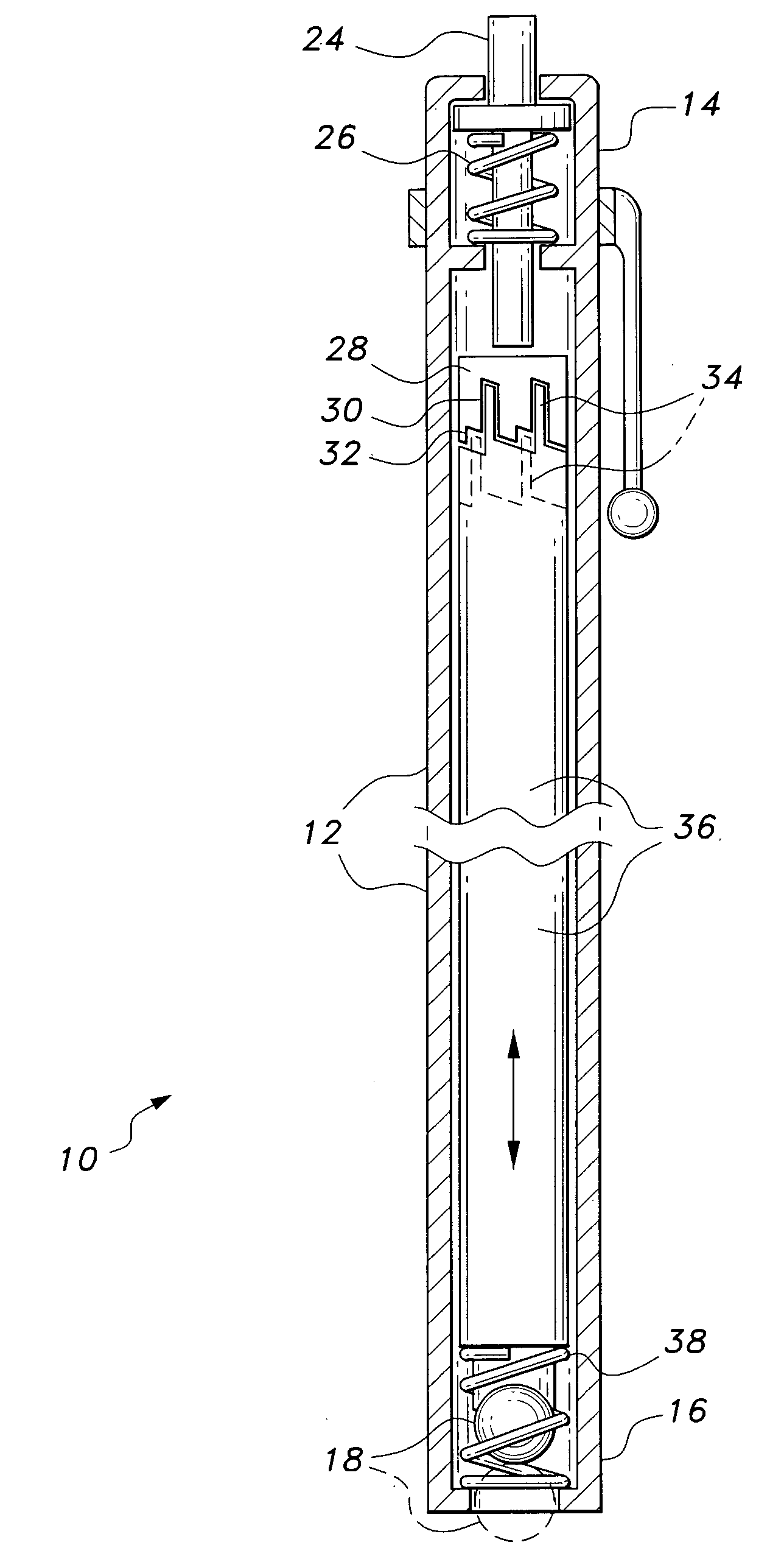
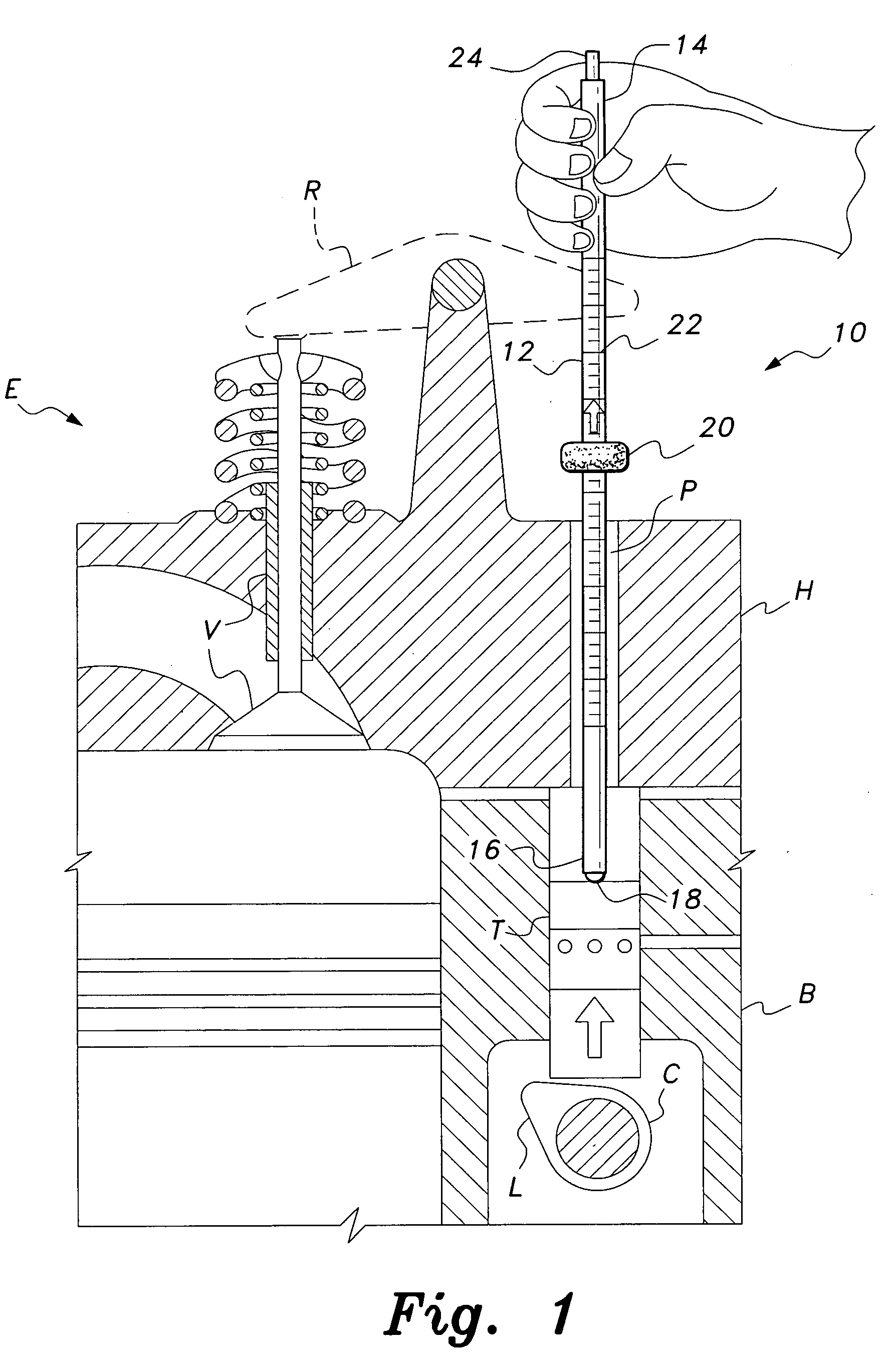
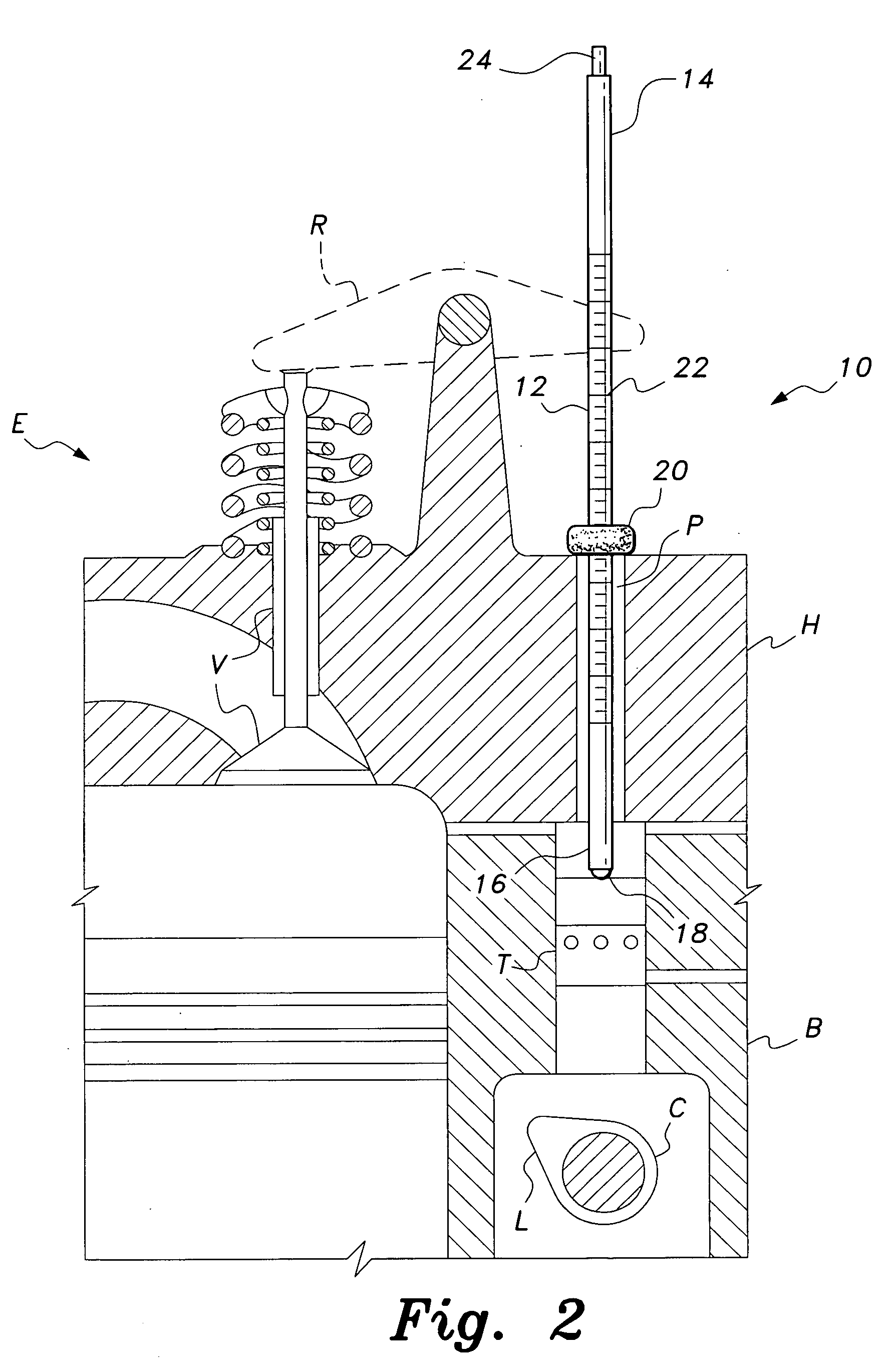
[0039] The present invention comprises a series of embodiments of a magnetic tool, with a primary function of the tool being the temporary retraction of a valve lifter for clearance from the cam lobes in an in-block camshaft, overhead valve (OHV) spark ignition or diesel engine. However, the present tool includes additional embodiments which enable it to perform other functions as well.

[0040]FIG. 1 of the drawings provides an environmental illustration of a first embodiment 10 of the present magnetic tool in use. The tool 10 of FIG. 1, as well as all of the other tool embodiments of the present invention, are based upon a narrow, elongate, rigid, hollow tubular shank 12 having a handgrip end 14 and an opposite working end 16. A small but strong magnet 18 is selectively extendible and retractable from the working end 16 of the tool shank 12. Various mechanisms may be provided for the magnet extension and retraction operation, as shown in FIGS. 3 through 5 and discussed further below...


PUM


Abstract

The magnetic tool has a narrow, elongate, rigid shank having a handgrip end and a selectively extendible and retractable magnet at the opposite working end. Various mechanisms are provided at the handgrip end to extend and retract the magnet. The working end of the tool may be provided with a polygonal (e.g., hexagonal, square, etc.) receptacle for the removable installation of a tool bit or square drive socket therein. The retracted magnet retains the bit or socket within the receptacle as desired. The magnetic tool is particularly well-adapted for insertion into a pushrod passage in the cylinder head of an overhead valve engine, for retracting a valve lifter away from the lobe of the camshaft to facilitate removal and replacement of the camshaft. A linear scale depth gauge may be provided, and an adjustably positionable collar may be provided to hold the tool with the lifter retracted.

Description

BACKGROUND OF THE INVENTION [0001] 1. Field of the Invention [0002] The present invention relates generally to magnetized tools of various types, and more specifically to an elongate tool having a selectively extendible and retractable magnetic tip. The present magnetic tool is particularly well adapted for use as a valve lifter or tappet raising tool for use in removing the camshaft from the block of an engine, but may be modified or adapted for other purposes as well. [0003] 2. Description of the Related Art [0004] Many, if not most, U.S. automotive and truck engines are constructed with the valve actuating camshaft located in a bore within the engine block, offset from the engine crankshaft. These engines universally use the overhead valve principle, with the valves being actuated by pushrods extending upwardly from the camshaft lobes and acting on rocker arms atop the cylinder head to actuate the valves. Such engines nearly universally use hydraulic tappets or lifters riding on ...

Claims


Application Information

Patent Timeline
Patent Type & Authority Applications(United States)
IPC IPC(8): B25J15/06
CPCB25B9/00H01F7/0257B25B23/12B25B11/002
Inventor ERNESTI, CARL J.
Owner ERNESTI CARL J
Why Eureka
Try Eureka