
Head mounted display with wave front modulator

a head mounted display and wave front technology, applied in the field of interactive paper, can solve the problems of poor depth cues, difficult to achieve the registration between the real world and the virtual imagery without, and the approach is somewhat inaccura

Inactive Publication Date: 2006-02-09
SILVERBROOK RES PTY LTD
View PDF17 Cites 556 Cited by
  • Summary
  • Abstract
  • Description
  • Claims
  • Application Information

AI Technical Summary

Benefits of technology

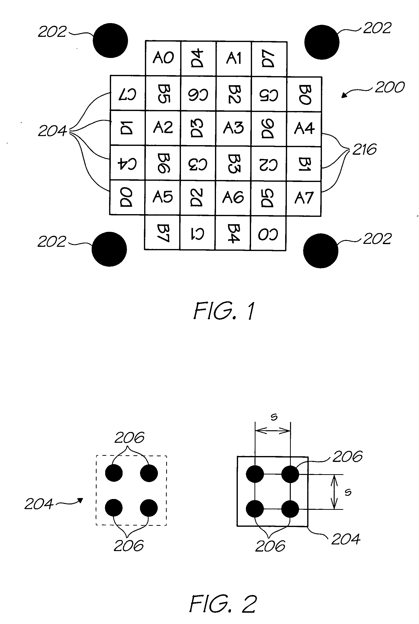
[0031] By providing a coded surface instead of sparse fiducials, the invention avoids tracking and ambiguity problems. The relatively dense coding allows the surface to be accurately positioned and oriented to maintain registration with the virtual imagery.
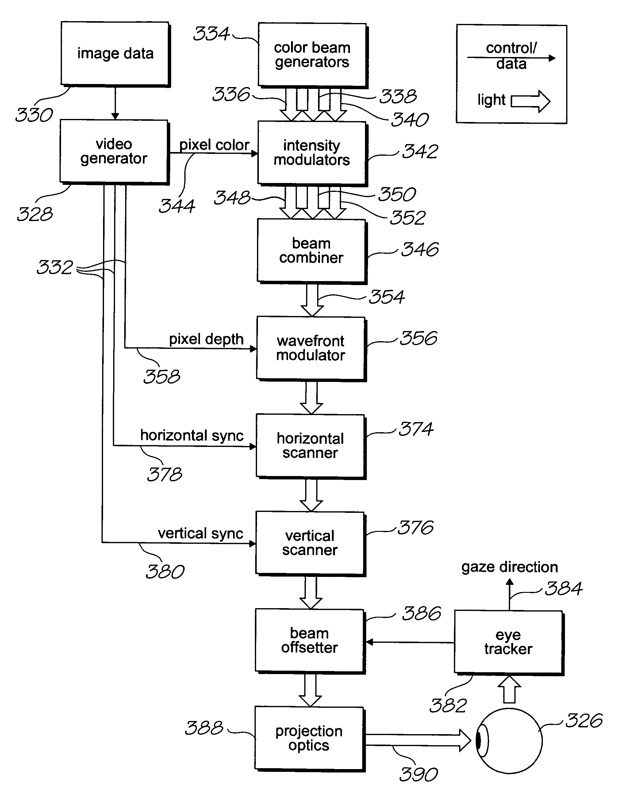
[0044] A virtual retinal display (VRD) projects a beam of light onto the eye, and scans the beam rapidly across the eye in a two-dimensional raster pattern. It modulates the intensity of the beam during the scan, based on a source video signal, to produce a spatially-varying image. The combination of human persistence of vision and a sufficiently fast and bright scan creates the perception of an object in the user's field of view.
[0049] the virtual retinal display accounts for any occlusions that at least partially obscure the user's view of the perceived location of the virtual imagery by using a spatial light modulator that blocks occluded parts of the wavefront and allows non-occluded parts of the wavefront to pass.

Problems solved by technology

It has the disadvantage that it is typically bulky and has a narrow field of view, and typically provides poor depth cues (i.e. a sense of depth or the distance from the eye to an object).
It has the disadvantage that registration between the real world and the virtual imagery is difficult to achieve without intrusive calibration procedures and sophisticated eye tracking.
A HMD often relies on inertial tracking to maintain registration during head movement, but this is a somewhat inaccurate approach.
The use of fiducials in the real world is less popular because fiducial tracking is usually not fast enough for typical user head movements, fiducials are typically sparsely placed making fiducial detection complex, and the fiducial encoding capacity is typically small which limits the number of individual fiducials that can uniquely identify themselves.
This can lead to fiducial ambiguity in large installations.

Method used


Image

  • Head mounted display with wave front modulator
  • Head mounted display with wave front modulator
  • Head mounted display with wave front modulator

Examples


Embodiment Construction

[0109] As discussed above, the invention is well suited for incorporation in the Assignee's Netpage system. In light of this, the invention has been described as a component of a broader Netpage architecture. However, it will be readily appreciated that augmented reality devices have much broader application in many different fields. Accordingly, the present invention is not restricted to a Netpage context.

[0110] Additional cross referenced documents are listed at the end of the Detailed Description. These documents are predominantly non-patent literature and have been numbered for identification at the relevant part of the description. The disclosures of these documents are incorporated by cross reference.

Netpage Surface Coding

Introduction

[0111] This section defines a surface coding used by the Netpage system (described in co-pending application Docket No.

[0112] NPS110US as well as many of the other cross referenced documents listed above) to imbue otherwise passive surfaces ...


PUM


Abstract

An augmented reality device for inserting virtual imagery into a user's view of their physical environment, the device comprising: a display device through which the user can view the physical environment; an optical sensing device for sensing at least one surface in the physical environment; and, a controller for projecting the virtual imagery via the display device; wherein during use, the controller uses wave front modulation to match the curvature of the wave fronts of light reflected from the display device to the user's eyes with the curvature of the wave fronts of light that would be transmitted through the device display if the virtual imagery were situated at a predetermined position relative to the surface, such that the user sees the virtual imagery at the predetermined position regardless of changes in position of the user's eyes with respect to the see-through display.

Description

FIELD OF THE INVENTION [0001] The present invention relates to the fields of interactive paper, printing systems, computer publishing, computer applications, human-computer interfaces, information appliances, augmented reality, and head-mounted displays. CO-PENDING REFERENCESNPS108USNPS109USNPS110US[0002]CROSS-REFERENCES10 / 81562110 / 81561210 / 81563010 / 81563710 / 81563810 / 81564010 / 81564210 / 81564310 / 81564410 / 81561810 / 81563910 / 81563510 / 81564710 / 81563410 / 81563210 / 81563110 / 81564810 / 81564110 / 81564510 / 81564610 / 81561710 / 81562010 / 81561510 / 81561310 / 81563310 / 81561910 / 81561610 / 81561410 / 81563610 / 81564911 / 04165011 / 04165111 / 04165211 / 04164911 / 04161011 / 04160911 / 04162611 / 04162711 / 04162411 / 04162511 / 04155611 / 04158011 / 04172311 / 04169811 / 04164810 / 81560910 / 81562710 / 81562610 / 81561010 / 81561110 / 81562310 / 81562210 / 81562910 / 81562510 / 81562410 / 81562810 / 91337510 / 91337310 / 91337410 / 91337210 / 91337710 / 91337810 / 91338010 / 91337910 / 91337610 / 91338110 / 986402IRB013US11 / 17281511 / 17281410 / 40987610 / 40984810 / 40984511 / 08476911 / 084742...

Claims


Application Information

Patent Timeline
IPC IPC(8): G09G5/00G02B30/27
CPCG02B26/06G02B27/017G02B2027/0123G06F3/0321G02B2027/0187G06F3/011G06F3/013G02B2027/014G02B27/0093H04N13/344G02B30/27G06F3/03545
Inventor LAPSTUN, PAULSILVERBROOK, KIA
Owner SILVERBROOK RES PTY LTD
Learn More