LCD apparatus for improved inversion drive

a technology of inversion drive and lcd apparatus, which is applied in the direction of instruments, static indicating devices, etc., can solve the problems of uneven brightness of display image of lcd apparatus, and undesirable flicker of lcd apparatus, so as to reduce undesirable uneven brightness of display panel

Inactive Publication Date: 2006-02-09
RENESAS ELECTRONICS CORP
View PDF11 Cites 34 Cited by
  • Summary
  • Abstract
  • Description
  • Claims
  • Application Information

AI Technical Summary

Benefits of technology

[0015] Independent control of the first and second polarity patterns used by the first and second source drivers allows avoiding irregularity in the polarities of the data signals at the border between the first and second regions, which are associated with the first and second source drivers. This effectively reduces undesirable uneven brightness on the display panel.

Problems solved by technology

One recent problem of LCD apparatuses adopting the dot inversion drive is that such LCD apparatuses often suffer from undesirable flicker, when displaying a specific pattern on the LCD panel.
This undesirably causes the flicker of the LCD apparatus.
Such LCD apparatuses, however, often exhibit uneven brightness of the displayed image at the borders between adjacent regions of the LCD panel driven by adjacent source drivers.
This may causes the irregularity of the data signal polarities when the number of the outputs of the individual source drivers 102 is inappropriate in view of the spatial cycle at which the polarities of the data signals are inverted.
As mentioned above, however, the fact that the source drivers each have 414 outputs undesirably causes the polarity irregularity problem.

Method used


Image

  • LCD apparatus for improved inversion drive
  • LCD apparatus for improved inversion drive
  • LCD apparatus for improved inversion drive

Examples


first embodiment

(Overall Structure)

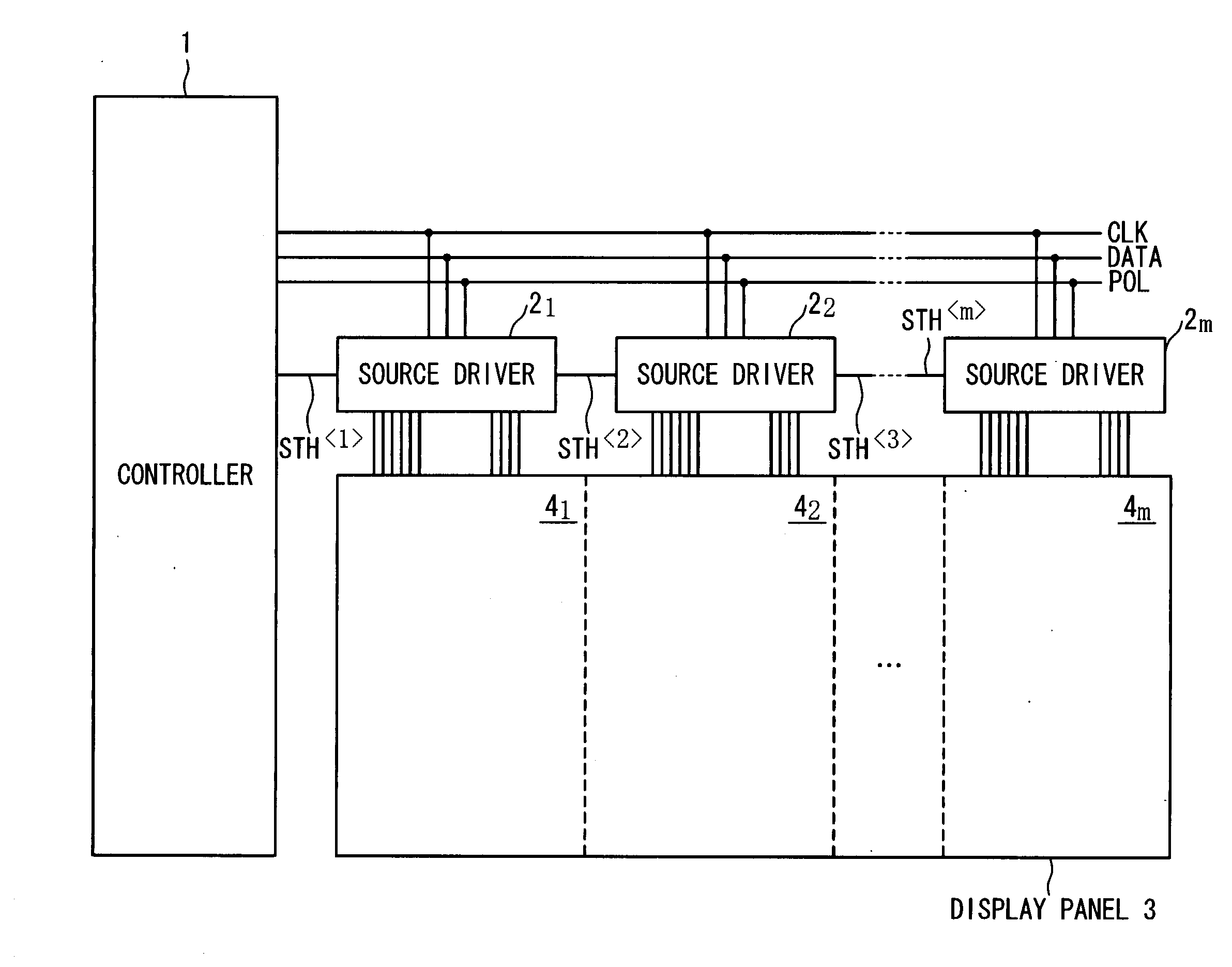
[0045] In a first embodiment of the present invention, as shown in FIG. 3, an LCD apparatus is composed of a controller 1, a set of m source drivers 21 to 2m, a display panel 3 within which pixels (not shown) are arranged in rows and columns. The controller 1 provides control for the source drivers 21 to 2m. The source drivers 21 to 2m are each designed to provide data signals for data lines within the display panel 3, and to thereby drive the pixels. The display panel 3 is composed of regions 41 to 4m associated with the source drivers 21 to 2m, respectively; the pixels within the region 4i are driven by the associated source driver 2i.

[0046] In detail, the controller 1 is designed to provide the source drivers 21 to 2m with pixel data DATA, a sync clock CLK, and a polarity signal POL. The pixel data DATA are indicative of grayscale levels of the respective pixels. In this embodiment, the pixel data DATA are n-bit data. The controller 1 forwards the pixel data...

first modification

1. First Modification

[0080] In an alternative embodiment, as shown in FIG. 11, the indication of the polarity pattern of the data signals is achieved through transferring polarity control bits 32 while the shift start pulses 31 are not transferred. In this embodiment, as shown in FIG. 12, the polarity pattern signal SPTN is developed in response to the polarity signal POL and the polarity control bits 32.

[0081] Preferably, the transfer of the polarity control bits 32 is performed after the generation of the associated shift start pulses 31. Transferring the polarity control bits 32 before the generation of the associated shift start pulses 31 requires providing control signals indicating latch timings of the polarity control bits 32 for the respective source drivers 21 to 2m. This undesirable increases the number of signal lines within the LCD apparatus. Transferring the polarity control bits 32 after the generation of the associated shift start pulses 31, on the contrary, allows t...

second modification

2. Second Modification

[0082] In order to further reduce the number of signal lines within the LCD apparatus, as shown in FIG. 13, the polarity patterns associated with the respective source drivers may be controlled on the control data transferred by the shift start signals STH to STH without using the polarity signal POL. As described above, the control data indicating the polarity pattern may be transferred as the pulse width of the shift start pulse 31. In this case, as shown in FIG. 14, the polarity pattern signal SPTN depends on only the pulse width of the shift start pulse 31. Alternatively, as shown in FIG. 15, the control data indicating the polarity pattern may be transferred as the polarity control bits 32 generated separately from the shift start pulse 31. In this case, as shown in FIG. 16, the polarity pattern signal SPTN depends on only the polarity control bits 32.


PUM


Abstract

A liquid crystal display apparatus is composed of a display panel including first and second regions adjacent to each other; a first source driver providing data signals for data lines within the first region of the display panel; and a second source driver providing data signals for data lines within the second region of the display panel. The first and second source drivers are designed so that a first polarity pattern of the data signals provided by the first source driver is controllable independently of a second polarity pattern of the data signals provided by the second source driver.

Description

BACKGROUND OF THE INVENTION [0001] 1. Field of the Invention [0002] The present invention generally relates to liquid crystal display devices, and more particularly, to inversion drive (or alternating drive) techniques used for LCD panel drive. [0003] 2. Description of the Related Art [0004] The inversion drive technique is widely used in the art, in order to avoid LCD burn-in, potentially caused by driving pixels within an LCD panel with DC voltage. The inversion drive technique involves periodically inverting the polarity of the data signal applied to each pixel. The time of the cycle at which the polarity of the data signal is inverted for each pixel is typically one frame, and such drive technique is called the frame inversion drive. The inversion drive reduces the DC component of the data signal applied to each pixel, and thereby effectively avoids LCD burn-in. [0005] The inversion drive technique is classified into two prominent types: one is the common constant drive techniqu...

Claims


Application Information

Patent Timeline
Patent Type & Authority Applications(United States)
IPC IPC(8): G09G3/36
CPCG09G3/3614G09G3/3685G09G2320/0233G09G2310/027G09G2310/0297G09G2310/0221G09G3/36G09G3/20
Inventor HIRATSUKA, HITOSHI
Owner RENESAS ELECTRONICS CORP
Why Eureka
Try Eureka