Polarizing plate protection film, polarizing plate, and liquid crystal display device

Active Publication Date: 2010-09-02
DAI NIPPON PRINTING CO LTD
View PDF3 Cites 31 Cited by
  • Summary
  • Abstract
  • Description
  • Claims
  • Application Information

AI Technical Summary

Benefits of technology

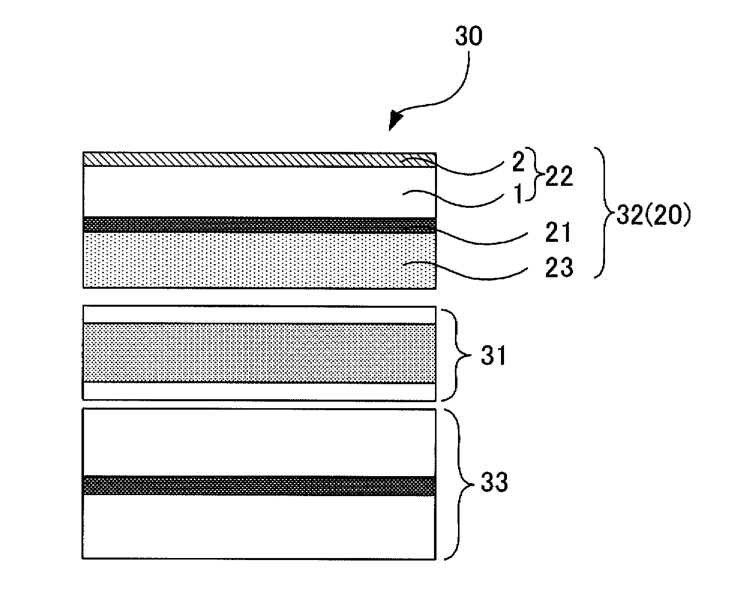
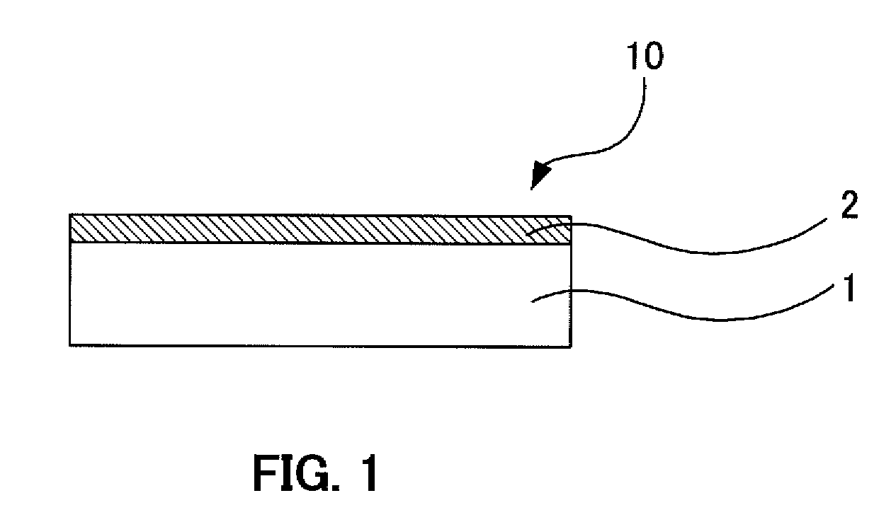
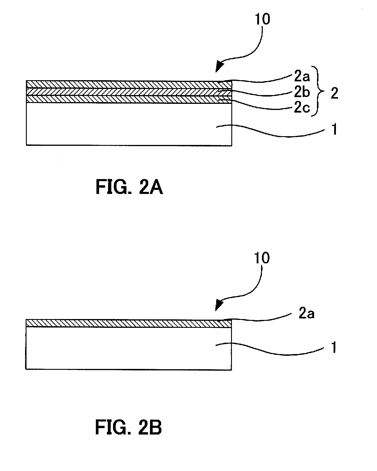
[0028]In the present invention, the above-mentioned polarizing plate protection film, i.e., the film comprising the transparent substrate and the refractive index difference-mitigating part, is used as the first polarizing plate protection film. Thereby, it becomes possible to prevent the generation of rainbow-like irregularities, even when a general-purpose film substituting a cellulosic ester film is used as the transparent substrate.
[0029]Thereby, it is poss

Problems solved by technology

However, as a member to catalyze the developing technical field of liquid crystal display devices, using of such cellulosic ester film encompass various problems.
However, large-scale equipments and specialized techniques are required to carry out such solution film-forming method including the solvent drying process and the like.
Thus, the producer of the cellulosic ester film is limited to those who possess the specialized techniques and the production of the cellulosic ester film cannot meet the demands of the developing liquid crystal display device technical field.
Therefore, continuing to relying on the cellulosic ester film as the polarizing plate protection film has a danger of hindering the development in the liquid crystal display device technical filed, which should be regarded as one of the major industries of Japan without exaggeration.
However, dichloromethane is suspected its risk to the human bod

Method used


Image

  • Polarizing plate protection film, polarizing plate, and liquid crystal display device
  • Polarizing plate protection film, polarizing plate, and liquid crystal display device
  • Polarizing plate protection film, polarizing plate, and liquid crystal display device

Examples


example 1

[0140]A PET film substrate A4300 (product name, manufactured by TOYOBO CO., LTD.) of 125 μm thickness was used as a transparent substrate. Here, the in-plane retardation (Re) of the transparent substrate had a distribution shown in FIG. 6 and its in-plane distribution was 38.2 nm. The in-plane distribution of the in-plane retardation (Re) was evaluated by using KOBRA® (manufactured by Oji Scientific Instruments) and measuring 20 points provided with 1 cm gap therebetween to an optional direction (measuring angle 0°, measuring wavelength 548.2 nm).

[0141]Further, a haze of the transparent substrate was 0.6% and all light transmission thereof was 90.1% (measured by HAZEMETER HM-150® manufactured by Murakami Color Research Laboratory).

[0142]A hard coat layer forming composition having the following composition was coated on the transparent substrate by bar coating and dried, and the solvent was subsequently removed. Then, the resultant was cured by using an ultraviolet irradiation devic...

example 2

[0154]Using the same transparent substrate as in Example 1, a low refractive index layer forming composition having the following composition was coated on the transparent substrate by bar coating and dried, and the solvent was subsequently removed. Then, the resultant was cured by using an ultraviolet irradiation device (manufactured by Fusion UV Systems Japan KK., light source: H bulb) under a condition of 100 mj / cm2 irradiation amount and a low refractive index layer having a refractive index of 1.51 and a thickness of 2 μm was formed. Thereby a polarizing plate protection film was obtained. The haze of the produced polarizing plate protection film was 8.9% and the all light transmission was 90.8%, and further, the anti-glare effect was confirmed.

(low refractive index layer forming composition)pentaerythritoltriacrylate (solid content 100%,30.0 parts by weightrefractive index 1.51):translucent silica fine particles (average particle 2.5 parts by weightdiameter 1.2 μm):IRGACURE 18...

example 3

[0159]A hard coat layer was formed on the transparent substrate by the same manner as in Example 1. Then, a low refractive index layer forming composition having the following composition was coated on the hard coat layer by bar coating and dried, and the solvent was subsequently removed. Then, the resultant was cured by using an ultraviolet irradiation device (manufactured by Fusion UV Systems Japan KK., light source: H bulb) under a condition of 100 mj / cm2 irradiation amount and a low refractive index layer having a refractive index of 1.39 and a thickness of 100 nm was formed. Thereby a polarizing plate protection film was obtained. The haze of the produced polarizing plate protection film was 0.6% and the all light transmission was 93.0%.

(low refractive index layer forming composition)surface-modified hollow silica fine particle MIBK11.0 parts by weightdispersion liquid (solid content 20% by weight):Opstar JN35 (product name, fluorine atom-containing10.0 parts by weightpolymer m...


PUM

PropertyMeasurementUnit
Angleaaaaaaaaaa
Nanoscale particle sizeaaaaaaaaaa

Abstract

A polarizing plate protection film and a polarizing plate which can restrain generation of rainbow-like irregularities and enables to produce an excellent quality liquid crystal display device when a commercially-available film is used as it is under commercially-available conditions or when a film produced by a common film forming method is used. The polarizing plate protection film includes: a transparent substrate; and a refractive index difference-mitigating part formed on the transparent substrate and provided with a low refractive index layer at its most outer layer, in which the low refractive index layer has a refractive index to the light transmitted through the transparent substrate smaller than that of the transparent substrate and bigger than that of the air. An in-plane distribution of the in-plane retardation (Re) of the transparent substrate is 5 nm or more.

Description

BACKGROUND OF THE INVENTION[0001]1. Field of the Invention[0002]The present invention relates to a polarizing plate protection film used for protecting a polarizer of a polarizing plate, a polarizing plate using the polarizing plate protection film, and a liquid crystal display device using the polarizing plate.[0003]2. Description of the Related Art[0004]In recent years, liquid crystal displays have been rapidly spread in place of conventional CRT displays, because of their characteristics such as electric power saving, lightweight and slimness. As shown in FIG. 11, for example, a general liquid crystal display device 100 comprises a backlight-side polarizing plate 102A, a display-side polarizing plate 102B, and a liquid crystal cell 101. In this structure, the polarizing plates 102A and 102B are each so configured that only linearly polarized light having an oscillation surface in a specific oscillation direction can be selectively transmitted, and placed opposite to each other in...

Claims


Application Information

Patent Timeline
IPC IPC(8): G02F1/1335G02B5/30B32B7/02B32B27/00B32B27/36G02B1/11
CPCG02B1/105Y10T428/24942G02F1/133528G02F2201/50G02B1/14G02B5/30G02F1/1335
Inventor KASHIMA, KEIJIKURODA, TAKASHIHAMADA, SATORU
Owner DAI NIPPON PRINTING CO LTD
Why Eureka
Try Eureka