Eureka AIR delivers breakthrough ideas for toughest innovation challenges, trusted by R&D personnel around the world.

System and method for dynamic sizing of cache sequential list

Inactive Publication Date: 2006-03-30
IBM CORP
View PDF6 Cites 33 Cited by
  • Summary
  • Abstract
  • Description
  • Claims
  • Application Information

AI Technical Summary

Benefits of technology

[0014] In another aspect, a data system is disclosed that uses a least recently used (LRU) caching scheme which in turn uses synchronous and asynchronous prefetch of data from a data storage device. The system avoids violation of stack property substantially without incurring additional sequential misses from cache.

Problems solved by technology

Relatively complex algorithms have been introduced which attempt to predict when a page will be needed, but commercial systems have rarely used very sophisticated prediction schemes, because sophisticated prediction schemes require an extensive history to be kept of page accesses.
This is cumbersome and expensive.
Furthermore, to be effective a prefetch must complete before the predicted request, requiring sufficient prior notice that may not be feasible to attain.
Also, long-term predictive accuracy may be low to begin with and can become worse with interleaving of a large number of different workloads.
Finally, for a disk subsystem operating near its peak capacity, average response time increases drastically with the increasing number of disk fetches, and, hence, low accuracy predictive prefetching which results in an increased number of disk fetches can in fact worsen the performance.
However, while seemingly simple, a good sequential prefetching algorithm and associated cache replacement policy, as critically recognized herein, is surprisingly difficult to achieve.
These unaccessed tracks within the current prefetch group can be accessed before the tracks in the newly prefetched group, so that, depending upon the amount of cache space available for sequential data, it can happen that some of these unaccessed tracks may be evicted from the cache before they are accessed, resulting in a sequential miss.
Hence, when LRU-based caching is used along with the above prefetching strategy, the resulting algorithm can violate the so-called stack property, and as a result, when the amount of cache space given to sequentially prefetched data increases, sequential misses do not necessarily decrease.
As further understood herein, at the cost of increasing sequential misses, both of the above problems can be hidden if (i) only synchronous prefetching is used or (ii) if both synchronous and asynchronous prefetching are used, setting the asynchronous trigger to always be the last track in a prefetched group, but of course the first approach amounts to foregoing all potential benefits of asynchronous prefetching, while the second approach can result in a sequential miss if the track being prefetched is accessed before it is in the cache.

Method used


Image

  • System and method for dynamic sizing of cache sequential list
  • System and method for dynamic sizing of cache sequential list
  • System and method for dynamic sizing of cache sequential list

Examples


Embodiment Construction

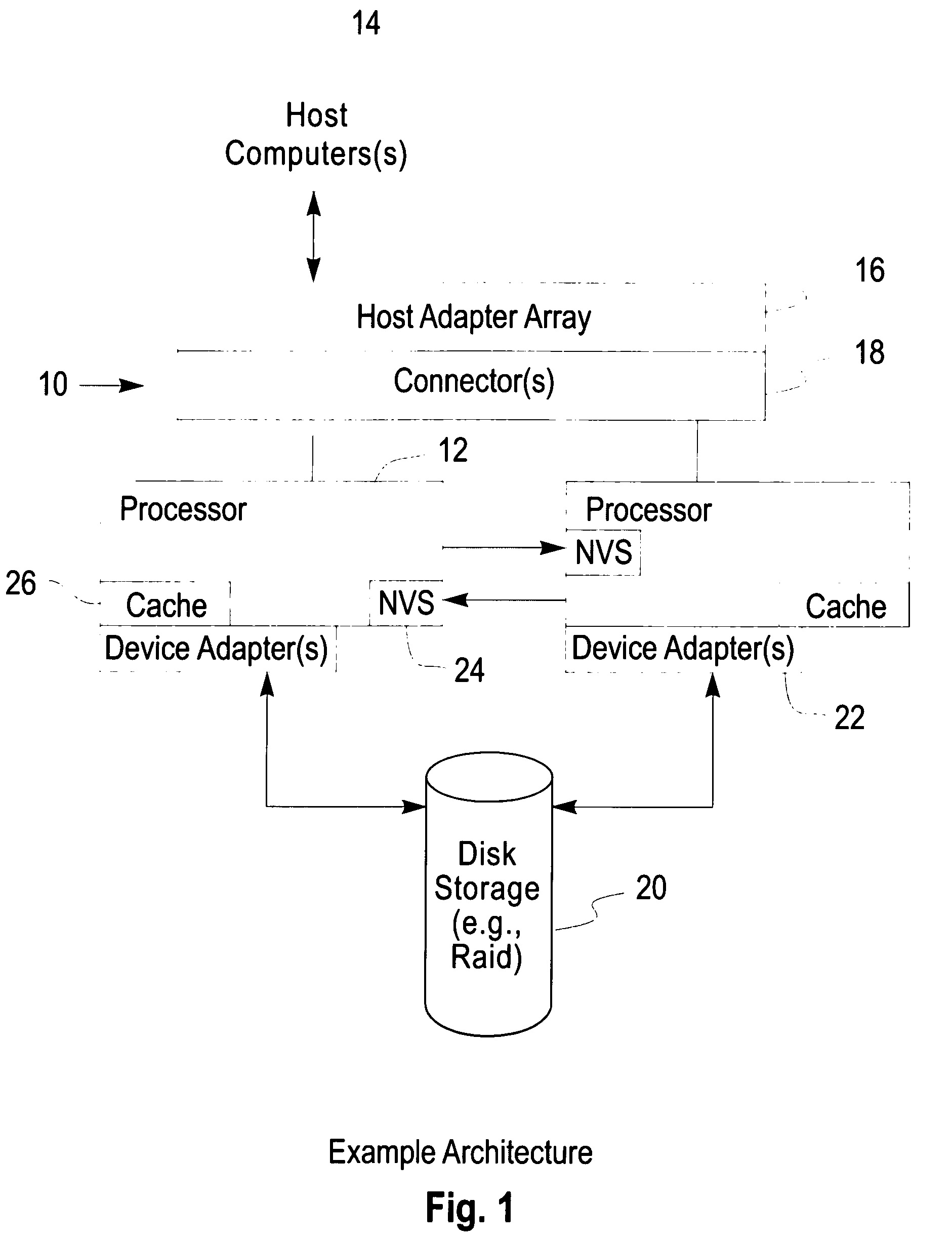
[0024] Referring initially to FIG. 1, a system is shown, generally designated 10, that illustrates one non-limiting environment in which the present invention can be used. In general, the present invention is a system for managing a data cache that caches data from a slower memory. For instance, the present invention may be implemented in database systems such as DB2 and Oracle, as well as RAID-based systems such as the present assignee's “Shark” system, as well as other systems, such as individual hard disk drives, etc. Accordingly, it is to be understood that while FIG. 1 illustrates one non-limiting implementation that has a “Shark” architecture, it is but representative of the environments that the present invention finds use. Thus, the present invention may be implemented in a file system, database system, or other system that must allocate space for variable-sized data objects. In one intended embodiment, the processor or processors (computers) of the present invention may be ...


PUM


Abstract

A self-tuning, low overhead, simple to implement, locally adaptive, novel cache management policy that dynamically and adaptively partitions the cache space amongst sequential and random streams so as to reduce read misses.

Description

FILED OF THE INVENTION [0001] The present invention relates generally to data caching. BACKGROUND [0002] Caching is a fundamental technique in hiding delays in writing data to and reading data from storage, such as hard disk drive storage. These delays can be referred to as input / output (I / O) latency. Because caching is effective in hiding I / O latency, it is widely used in storage controllers, databases, file systems, and operating systems. [0003] A cache thus may be defined as a high speed memory or storage device that is used to reduce the effective time required to read data from or write data to a lower speed memory or device. A modern storage controller cache typically contains volatile memory used as a read cache and a non-volatile memory used as a write cache. The effectiveness of a read cache depends upon its “hit” ratio, that is, the fraction of requests that are served from the cache without necessitating a disk trip (which represents a “miss” in finding data in the cache)...

Claims


Application Information

Patent Timeline
IPC IPC(8): G06F12/00
CPCG06F12/0862G06F12/123G06F12/0866
Inventor GILL, BINNY SHERMODHA, DHARMENDRA SHANTILAL
Owner IBM CORP
Why Eureka
Eureka Blog
Learn More