Imaging apparatus and imaging system

a technology of imaging apparatus and image, applied in the field of imaging apparatus and imaging system, can solve the problems of difficult carrying, thicker radiation imaging apparatus, irregular photographed image, etc., and achieve the effect of preventing irregular photographed imag

Active Publication Date: 2016-10-11
CANON KK
View PDF10 Cites 36 Cited by
  • Summary
  • Abstract
  • Description
  • Claims
  • Application Information

AI Technical Summary

Benefits of technology

[0006]An object of the present invention is to provide an imaging apparatus and an imaging system that, without being increased in size, have an AEC function that can prevent irregularities in photographed images.
[0008]According to the present invention, an imaging apparatus can be provided that, without being increased in size, has an AEC function that can prevent irregularities in photographed images.

Problems solved by technology

Consequently, in the case of a portable radiation imaging apparatus, there is the problem that the radiation imaging apparatus becomes thicker and is difficult to carry.
When the AEC sensors are disposed between pixels, there is the problem that irregularities arise in photographed images because the pixel layout is uneven in regions where the AEC sensors are disposed.

Method used


Image

  • Imaging apparatus and imaging system
  • Imaging apparatus and imaging system
  • Imaging apparatus and imaging system

Examples


first embodiment

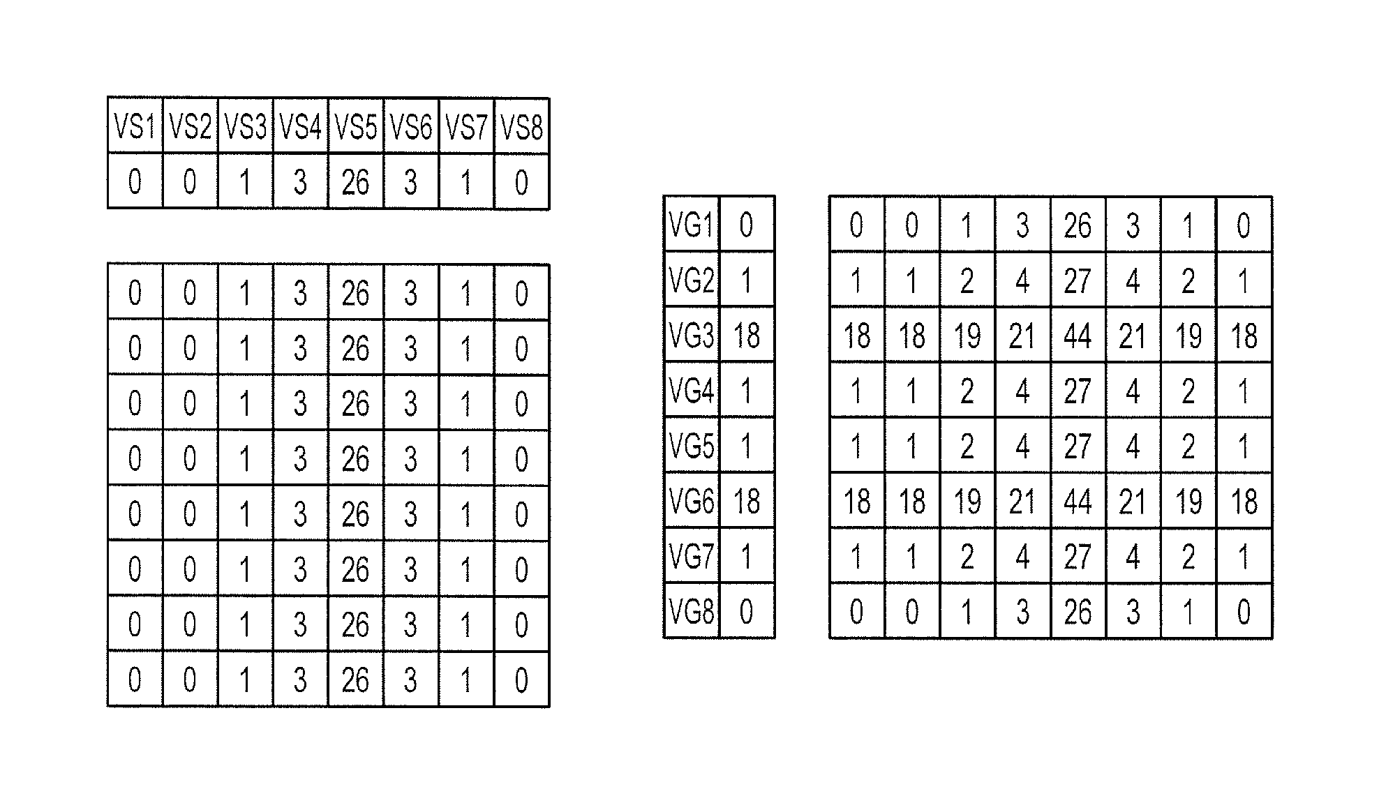
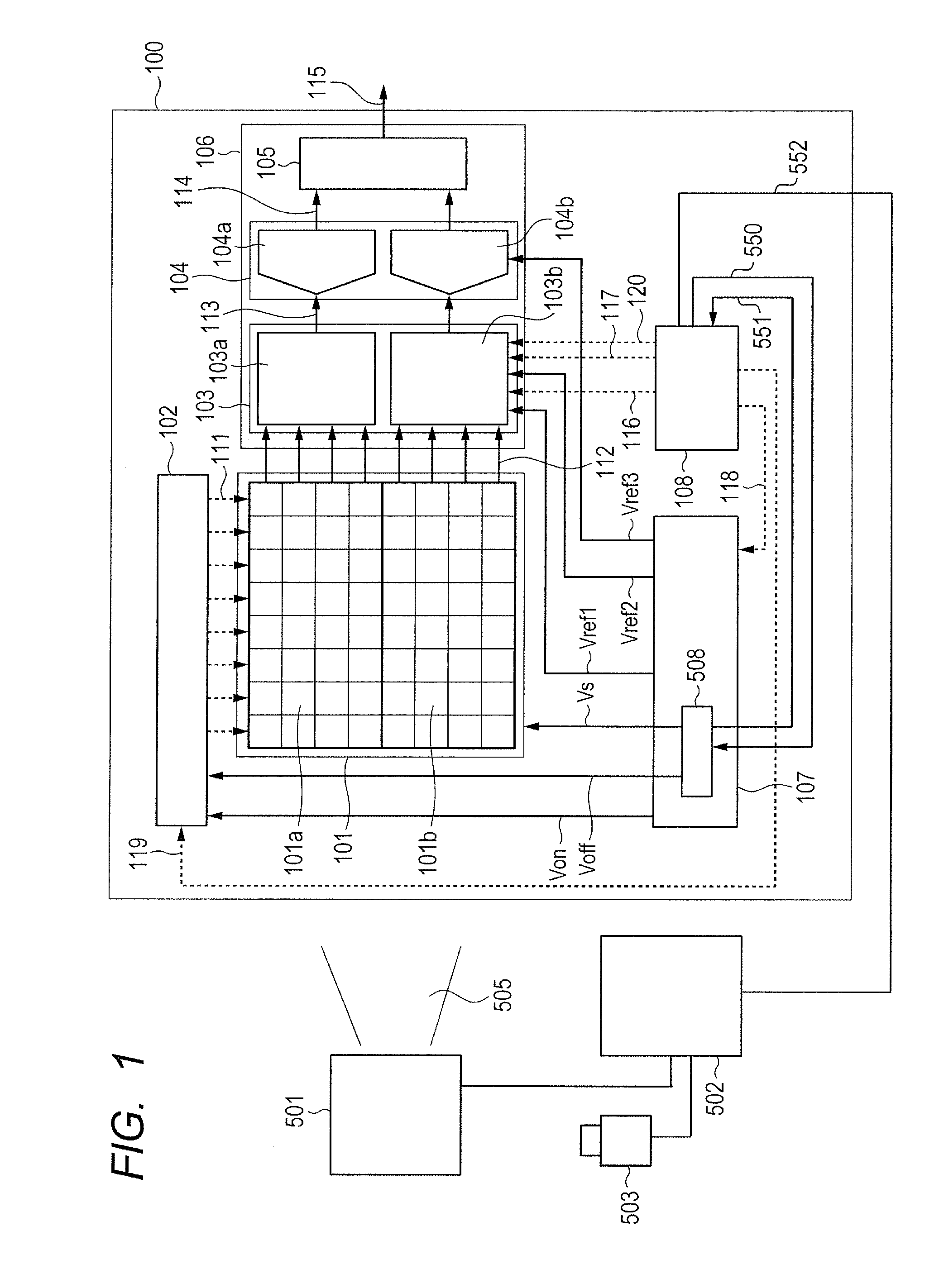
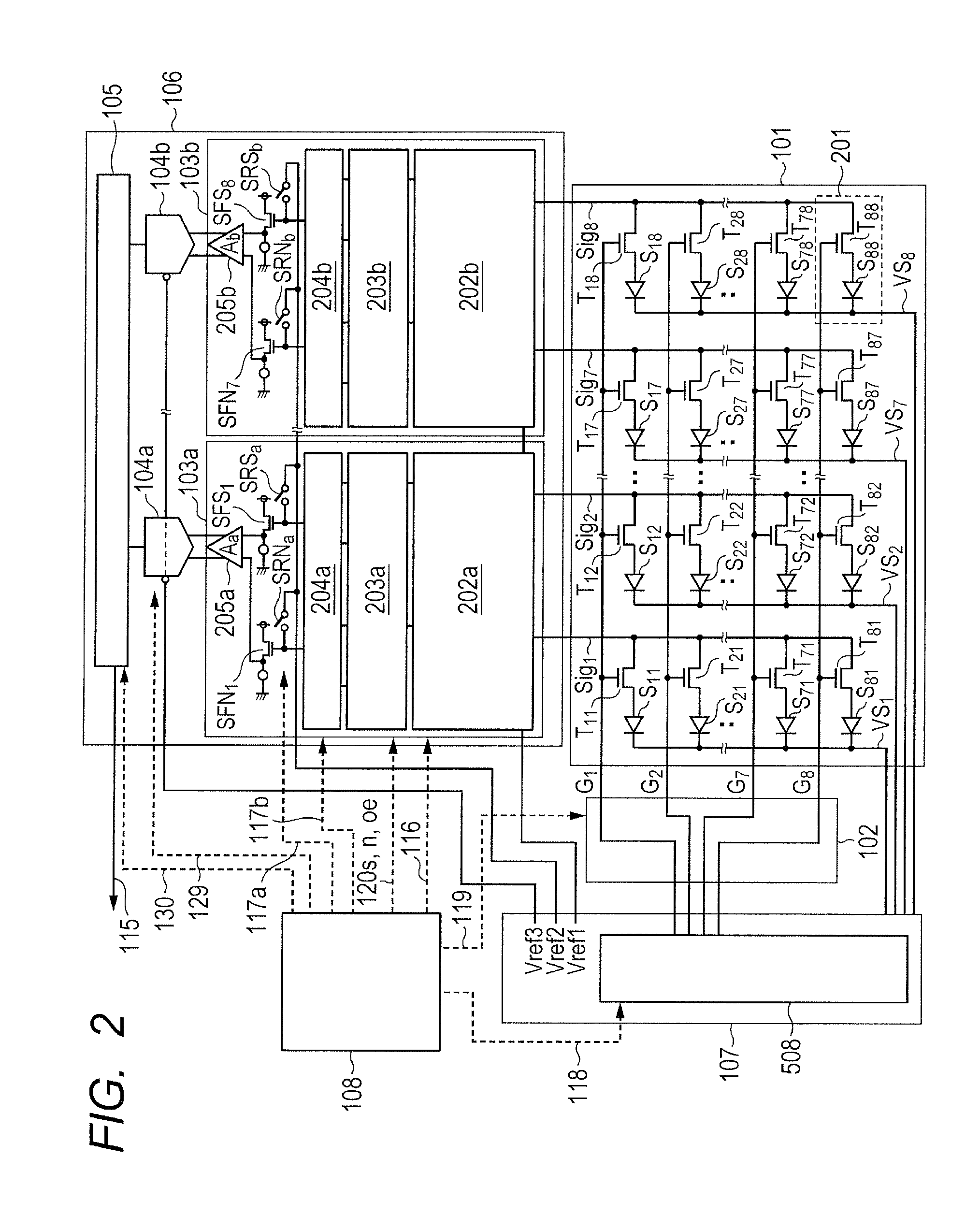
[0025]FIG. 1 is a block diagram of an imaging system including an imaging apparatus and an X-ray generating apparatus according to a first embodiment of the present invention. The imaging system can be used for diagnosis for medical treatment or for nondestructive inspections for industrial use. An imaging apparatus 100 includes a detection unit 101 that includes a plurality of pixels for converting radiation or light into an analog electrical signal that are arranged in a matrix shape, and a drive circuit 102 that drives the detection unit 101 to output an analog electrical signal from the detection unit 101. The term “radiation” includes electromagnetic waves such as X-rays and γ-rays, and α-rays and β-rays. According to the present embodiment, to simplify the description it is assumed that the detection unit 101 includes pixels arranged to form 8 rows and 8 columns and is divided into is a first pixel group 101a and a second pixel group 101b that each includes four pixel columns....

second embodiment

[0042]FIG. 9 is a view that illustrates a configuration example of the imaging apparatus 100 according to a second embodiment of the present invention. Note that elements in FIG. 9 having the same configuration as that described in the first embodiment are assigned the same reference numerals, and detailed descriptions thereof are omitted. In the first embodiment, the sensor bias lines VS1 to VS8 were wired commonly to a single column and the drive lines G1 to G8 were wired commonly to a single row. When a large amount of X-rays is irradiated at a part of the detector 101 and the output of a corresponding column or row increases, and it is not possible to accurately read the value of a portion at which a small amount of X-rays was irradiated in the same column. Therefore, according to the second embodiment, the sensor bias lines VS1 to VS8 are divided into two groups on the upper and lower sides, namely, sensor bias lines VSU1 to VSU8 and VSD1 to VSD8, and the drive lines G1 to G8 a...

third embodiment

[0044]FIG. 10 is a view that illustrates a configuration example of the imaging apparatus 100 according to a third embodiment of the present invention. Note that elements in FIG. 10 that have the same configuration as that described in the first embodiment are assigned the same reference numerals, and detailed descriptions thereof are omitted. In the first embodiment, because the arrangement of the lines is such that the sensor bias lines VS1 to VS8 and the drive lines G1 to G8 are orthogonal to each other, back-projection processing is performed from two directions. According to the third embodiment, the sensor bias lines VS1 to VS7 are wired in a diagonal direction. The sensor bias current monitor circuit units MVS1 to MVS7 monitor currents that flow in the sensor bias lines VS1 to VSD7 that extend in the diagonal direction, and output the monitoring results to the filter unit 560. The drive line current monitor circuit units MVG1 to MVG4 monitor currents that flow in the drive li...


PUM


Abstract

An imaging apparatus has an AEC function that can prevent irregularities in photographed images, without being increased in size. The imaging apparatus comprises a plurality of pixels arranged in a matrix shape, each of the plurality of pixels including a conversion element for converting radiation or light into an electric charge, a plurality of lines that are connected to the plurality of pixel units and that extend in different directions to each other, a current monitor circuit that monitors currents flowing in the plurality of lines, and an arithmetic unit that calculates a two-dimensional distribution by performing back-projection processing with respect to the currents flowing in the plurality of lines monitored by the current monitor circuit.

Description

BACKGROUND OF THE INVENTION[0001]1. Field of the Invention[0002]The present invention relates to an imaging apparatus and an imaging system.[0003]2. Description of the Related Art[0004]In recent years, radiation imaging apparatuses including a flat panel detector (hereinafter abbreviated as “FPD”) formed of a semiconductor material have started to be put to practical use as photographing apparatuses that are used for medical diagnostic imaging or nondestructive inspection using X-rays. The radiation imaging apparatuses that use an FPD are capable of digital photographing in which radiation such as X-rays that were transmitted through a subject such as a patient are converted into analog electrical signals at the FPD, and the analog electrical signals are subjected to analog-to-digital conversion to acquire digital image signals. The FPDs that are used in such radiation imaging apparatuses are broadly divided into direct-conversion type FPDs and indirect-conversion type FPDs. A direc...

Claims


Application Information

Patent Timeline
Patent Type & Authority Patents(United States)
IPC IPC(8): A61B6/00H05G1/38H04N5/32
CPCA61B6/42H04N5/32A61B6/542H05G1/38
Inventor TAKENAKA, KATSUROKAMESHIMA, TOSHIOYAGI, TOMOYUKISATO, SHOIWASHITA, ATSUSHISATO, ERIKOOKADA, HIDEYUKIRYU, TAKUYA
Owner CANON KK
Why Eureka
Try Eureka