USB cable device, USB subsystem and USB drive devices

a technology of usb subsystem and usb port, which is applied in the direction of liquid/fluent solid measurement, instruments, transportation and packaging, etc., can solve the problems of inability to apply conventional technology for filling up power shortages by, insufficient current supply capability of usb port of personal computer or pc-card usb hub,

Inactive Publication Date: 2008-05-29
FUJITSU LTD
View PDF4 Cites 33 Cited by
  • Summary
  • Abstract
  • Description
  • Claims
  • Application Information

AI Technical Summary

Benefits of technology

[0016]It is an object of the present invention to provide a USB cable device, a USB subsystem and USB drive devices which permit ensuring a pow

Problems solved by technology

When operating a USB drive device by bus power, a USB port of a personal computer or a PC-card USB hub does not have in some cases a sufficient current supply ability.
It is not however desirable to use an AC adapter from the point of view of the weight and the space when considering an environment in which an AC power supply is not applicable and portability.
However, the conventional technology for filling up the power shortage by a USB suffers from the following problems.
First of all, the technology of providing a power supply capacity expanding function o the simplified type using a super capacitor as a USB drive device requires much time for charging the super capacitor and cannot be applied in a continuous use. Because of the high cost and the large scale in size, it is not commonly applicable.
The technology of providing a cable comprising two integrated cables with an

Method used


Image

  • USB cable device, USB subsystem and USB drive devices
  • USB cable device, USB subsystem and USB drive devices
  • USB cable device, USB subsystem and USB drive devices

Examples


Embodiment Construction

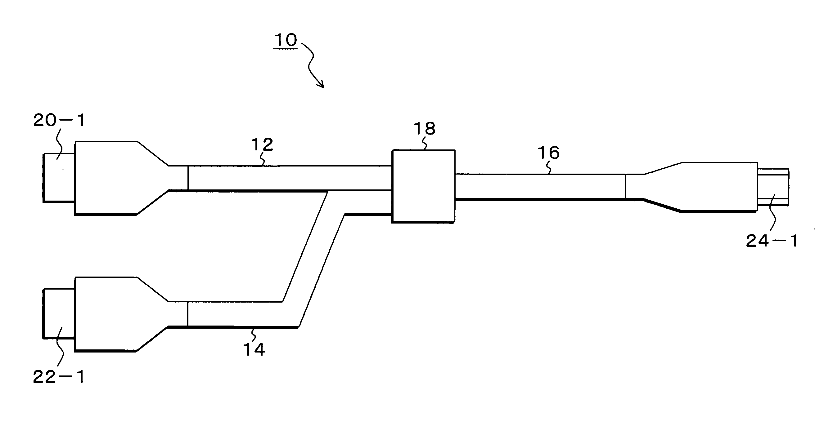
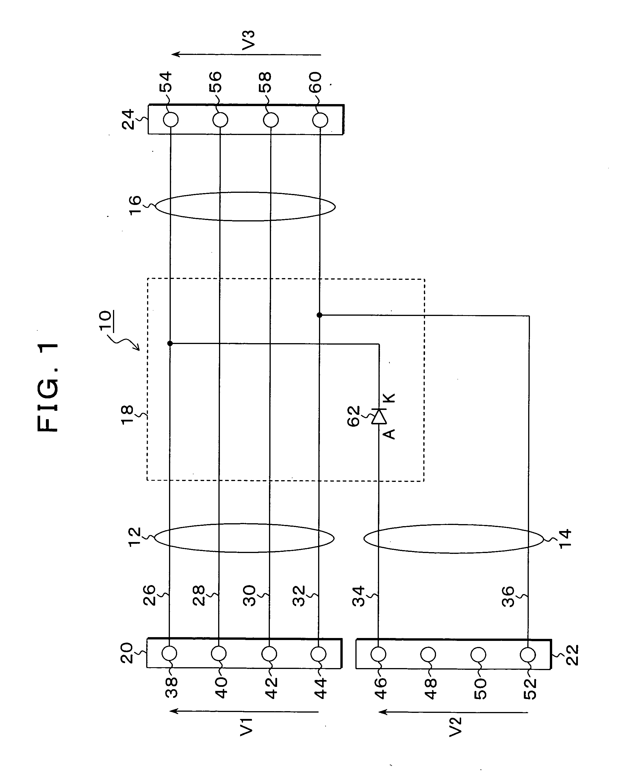
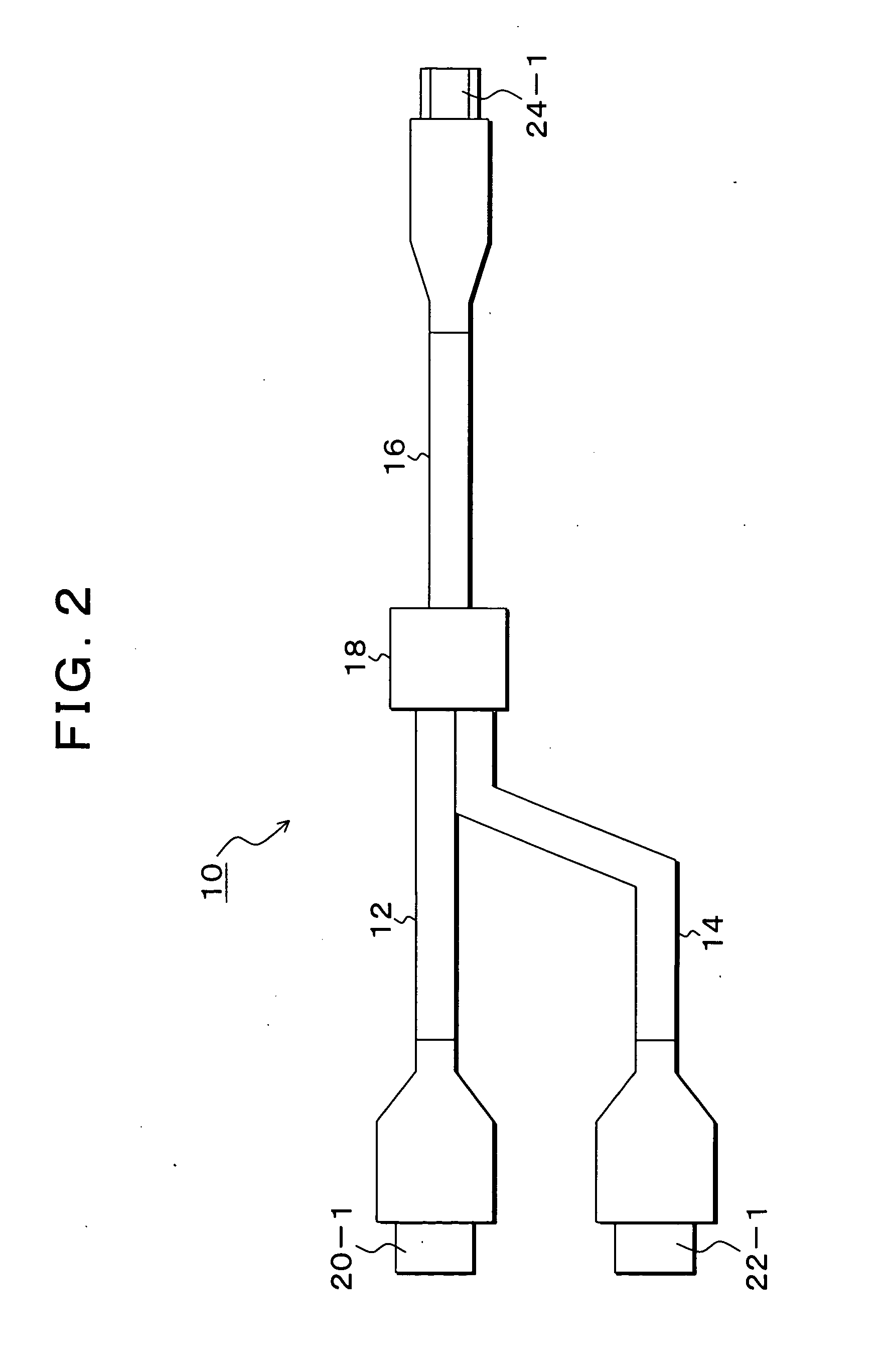
[0072]FIG. 1 is a circuit diagram illustrating an embodiment of the USB cable device of the present invention. In FIG. 1, the USB cable device 10 of this embodiment comprises a main cable 12, an auxiliary cable 14, a drive cable 16 and a connection module 18. The main cable 12 has a positive power line (VDD line) 26 prescribed by the USB Rules, a negative power line (GND line) 32 forming a pair therewith, a positive signal line (positive DATA line) 28, and a negative signal line (negative DATA line) 30 forming a pair therewith. The main cable 12 has at an end a connector 20 for connecting to a host USB port of a host such as a personal computer. The connector 20 has a positive power terminal 38, a positive signal terminal 40, a negative signal terminal 42 and a negative power terminal 44. The auxiliary cable 14 has a positive power line 26 and a negative power line 32, but not signal lines corresponding to the positive signal line 28 and the negative signal line 30 of the main cable...


PUM


Abstract

The main cable and the drive cable each incorporates a positive power line, a negative power line, a positive signal line and a negative signal line. The main cable is connected to the USB ort of the host apparatus with the connector, and the drive cable is connected to the USB ort of the USB drive device with the connector. In the connector module, the diode is inserted into the positive power line of the auxiliary cable, and the cathode side thereof is connected to the positive power line side of the mutually connected main cable and drive cable.

Description

[0001]This application is a priority based on prior application No. JP 2006-197937 filed Jul. 20, 2006, in Japan.BACKGROUND OF THE INVENTION[0002]1. Field of the Invention[0003]The present invention relates to a USB cable device, a USB subsystem and USB drive devices. More particularly, the invention relates to a USB cable device, a USB subsystem and USB drive devices for supplying source power necessary for USB drive devices from two USB ports of a higher-level equipment.[0004]2. Description of the Related Art[0005]Conventionally, as an interface for externally connecting various peripheral devices for a personal computer, USBs (Universal Serial Buses) are widely used. A USB can cause operation by supplying power to peripheral devices by having power supply lines in addition to signal lines and can provide an advantage of not requiring a special power supply for peripheral devices. It is thus popularly used because of the convenience of not requiring a special power supply not only...

Claims


Application Information

Patent Timeline
IPC IPC(8): G06F1/26H02J1/10
CPCG06F1/266
Inventor MINAMI, AKIRA
Owner FUJITSU LTD
Why Eureka
Try Eureka