Switching power supply circuit

Inactive Publication Date: 2010-04-08
HEP TECH
View PDF6 Cites 9 Cited by
  • Summary
  • Abstract
  • Description
  • Claims
  • Application Information

AI Technical Summary

Benefits of technology

[0013]The object of this invention is to provide a cheap and compact switching power supply circuit with properties equivalent to the prior dir

Problems solved by technology

A particular problem is that when the output direct-current

Method used


Image

  • Switching power supply circuit
  • Switching power supply circuit
  • Switching power supply circuit

Examples


Embodiment Construction

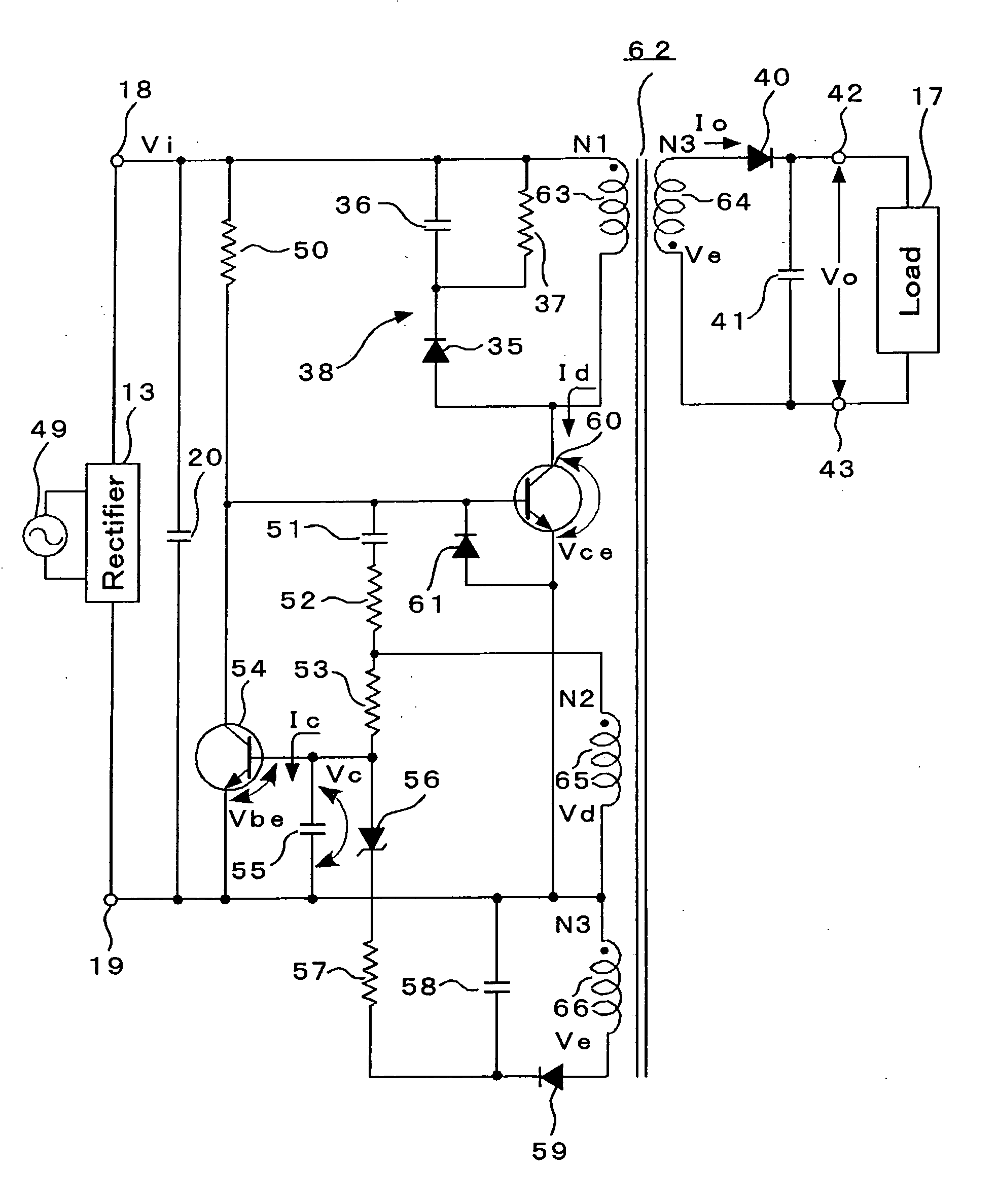
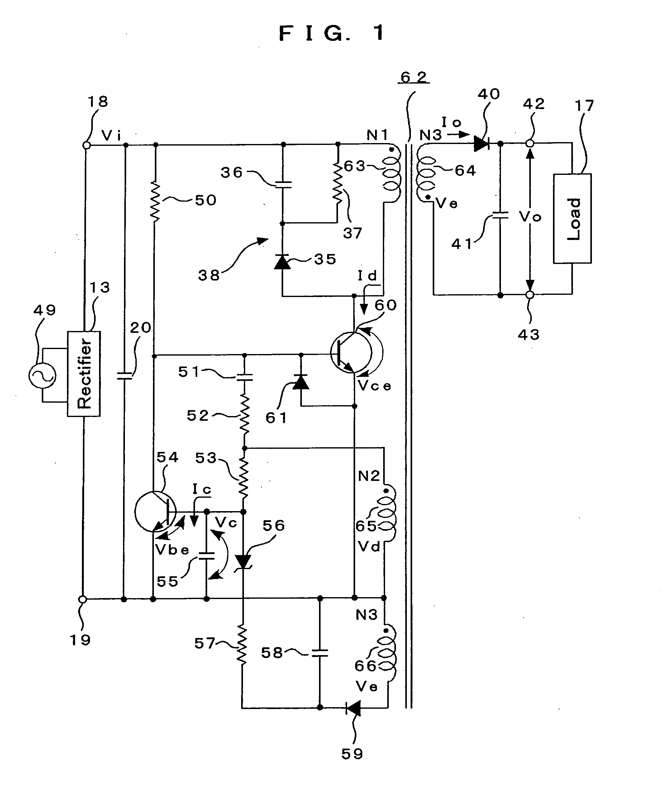
[0032]The switching power supply circuit of the invention comprises the first switching element 60 having the fly-back transformer 62 with the magnetizing coil 63 and the drive coil 65 at the primary side and the output coil 64 at the secondary side and the bipolar transistor self-oscillating when a voltage is applied from said drive coil 65 and then magnetizing said magnetizing coil 63, the second switching element 54 with the bipolar transistor controlling the switching time of the first switching element 60, and the timing condenser 55 connected between the base and emitter of the second switching element 54 and supplied a current from said drive coil 65 through the impedance circuit; adopts RCC type in which a direct-current voltage rectified an AC voltage is supplied to said magnetizing coil 63 and output from said output coil 64 by switching; and equips the sensing coil 66 connected magnetically closely with said output coil 64 in said flyback transformer 62. The sensing coil ...


PUM


Abstract

In a RCC type switching power supply circuit, a sensing coil connected magnetically closely with an output coil is equipped in a fly-back transformer. The sensing coil is connected with a timing condenser through a Zener diode and an alternate current voltage output from the sensing coil is rectified and smoothed. Then, the difference between a detection voltage detected as a direct current voltage of the secondary side and the basic voltage of the Zener diode is supplied to the timing condenser to change the discharge/charge time and then change the timing of the switching of a first switching element in order to control the switching time of the first switching element. At the same time, applying the voltage which results from rectifying and smoothing the output voltage from the sensing coil, the charge and discharge of the timing condenser at the non-loading time is controlled in order to prolong the cycle of the switching oscillation and consequently, reduce the power loss.

Description

TECHNICAL FIELD[0001]This invention relates to a switching power supply circuit with a relatively low output of 50 W or less which approximates the output voltage and current properties of linear AC adopters as shown in FIG. 5 and which enables to reduce a power loss at a non-loading time (while a slight current runs) and be provided with a cheap price.BACKGROUND ART[0002]FIG. 5 shows an initial direct-current power supply circuit called linear AC adopter. In FIG. 5, a commercially available alter later voltage Vi input into the part between a AC input terminal 10 and 11 is converted to a prescribed voltage at a transformer 12, rectified at a full-wave rectifier 13, and smoothed at a smoothing condenser 14. Then, a direct-current voltage Vo and direct-current Io are supplied to a load 17 through direct-current output terminals 15 and 16.[0003]In the simple and cheap power supply circuit of direct current called linear AC adopter shown in FIG. 5, when the input alternate-current volt...

Claims


Application Information

Patent Timeline
IPC IPC(8): H02M7/217
CPCH02M3/33523H02M2001/0032Y02B70/16Y02B70/1491H02M2001/0048H02M1/0032H02M1/0048Y02B70/10
Inventor NAKAI, KOICHI
Owner HEP TECH
Why Eureka
Try Eureka