Converter station

a technology of converter station and transformer, applied in the field of converter station, can solve problems such as the affect of parts of the pole, and achieve the effect of increasing reliability

Inactive Publication Date: 2009-07-02
ABB POWER GRIDS SWITZERLAND AG
View PDF5 Cites 10 Cited by
  • Summary
  • Abstract
  • Description
  • Claims
  • Application Information

AI Technical Summary

Benefits of technology

[0021]The invention also relates to an HVDC (High Voltage Direct Current) transmission system having converter stations according to the invention, which may benefit from the favourable construction of said converter stations and increased reliability thereof.

Problems solved by technology

This means that if one of the four sources fails only this particular pole will be affected.

Method used


Image

  • Converter station
  • Converter station
  • Converter station

Examples


Embodiment Construction

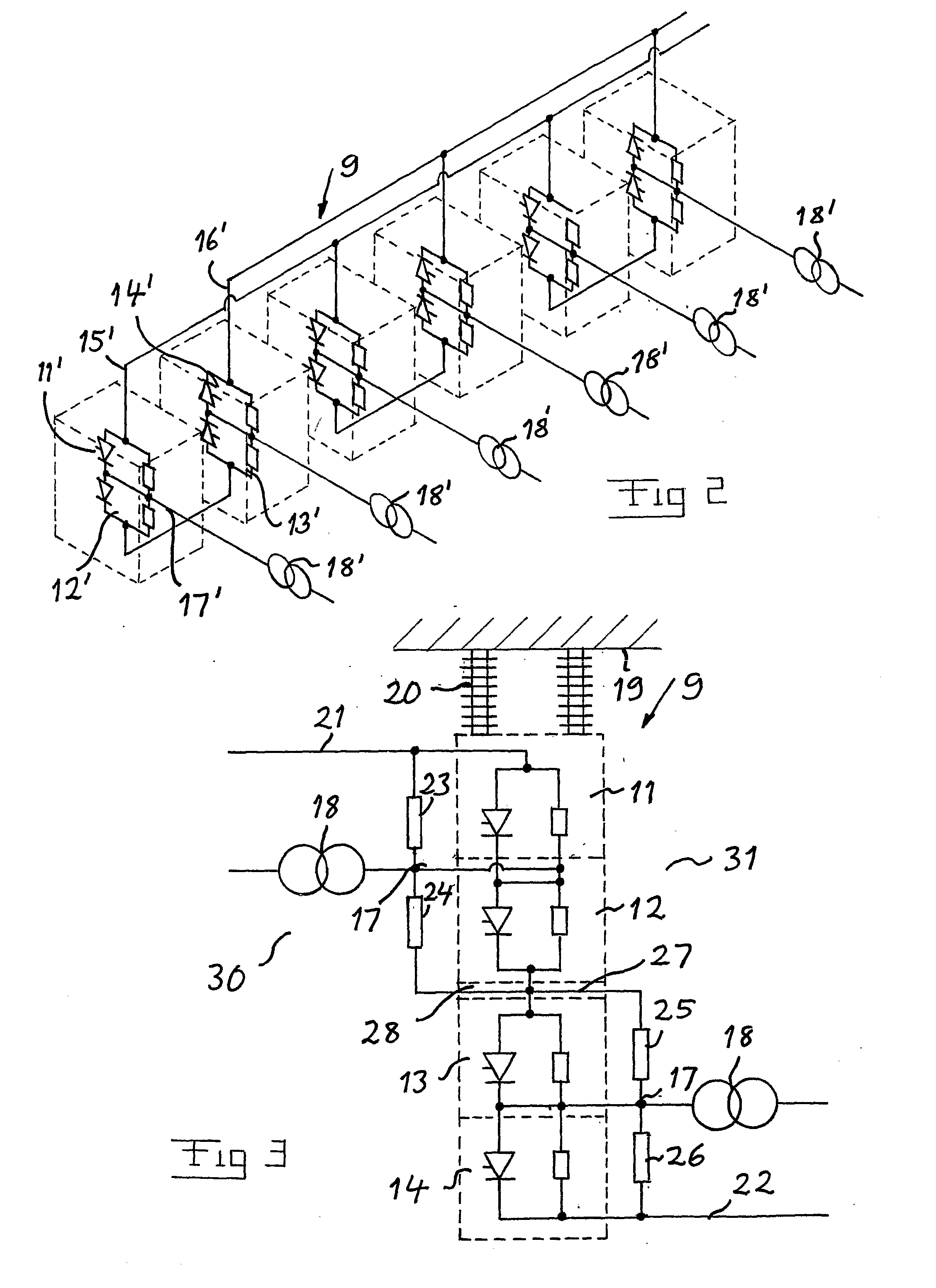
[0031]FIG. 3 illustrates schematically an advantageous structure of a converter in a converter station according to the invention. This converter is shown from one end, so that only one of three columns arranged in a row is shown. Accordingly, this is a 12-pulse bridge converter having the series connection of four converter valves 11-14 arranged in one column on top of each other. Such a column is here shown to be insulated with respect to the roof 19 of a converter valve hall by an insulation member 20. The DC-side of the converter is connected to said converter column on opposite sides thereof by a connection 21 to a pole of the HVDC transmission line and a connection 22 to a neutral bus of the converter station. Surge arresters 23-26 are connected in series between said DC-connections 21, 22 with one surge arrester connected in parallel with each converter valve for protection thereof against over-voltages. One part of the series connection of surge arresters, namely two of them...


PUM


Abstract

A converter station for connecting an AC system to an HVDC transmission line. At least two converters are arranged in two separate converter valve halls. The station includes a separate control device configured to control of each converter and an auxiliary power source configured to provide auxiliary power for each converter. A separate overall control configured to control the overall operation conditions is arranged for each converter making each converter self supporting. The converter valve halls are separated by a substantial space.

Description

TECHNICAL FIELD OF THE INVENTION AND PRIOR ART[0001]The present invention relates to a converter station for connecting an AC system to an HVDC transmission line, said station comprising at least two converters arranged in separate converter valve halls and each having a DC-side for connection to said transmission line and an AC-side connected to said AC system, said converter station comprising a control arrangement adapted to control the operation of said converters, means for providing the converters with auxiliary power as well as means for controlling the overall operation conditions of the converters, such as cooling of components thereof.[0002]The invention is not restricted to any particular levels of voltage between earth and a pole of said HVDC (High Voltage Direct Current) transmission line, but it is especially applicable to such voltages above 500 kV, which means that said transmission line transmits a substantial power and the transmission system to which the converter...

Claims


Application Information

Patent Timeline
Patent Type & Authority Applications(United States)
IPC IPC(8): H02M7/10
CPCH02J3/36Y02E60/60H02J3/38
Inventor KARLSSON, PER H.BERGLUND, SVENNORDSTROM, NILS
Owner ABB POWER GRIDS SWITZERLAND AG
Why Eureka
Try Eureka