Uninterruptible power supply system

a power supply system and uninterruptible technology, applied in the emergency power supply arrangement, transportation and packaging, energy industry, etc., can solve the problem of lowering the risk of load deactivation, and achieve the effect of enhancing the efficiency of utilizing the plurality of uninterruptible power supply devices connected in parallel, reducing power losses, and reducing power consumption

Active Publication Date: 2014-02-27
TOSHIBA MITSUBISHI-ELECTRIC IND SYST CORP
View PDF1 Cites 12 Cited by
  • Summary
  • Abstract
  • Description
  • Claims
  • Application Information

AI Technical Summary

Benefits of technology

[0010]According to the uninterruptible power supply system in accordance with the present invention, in the case where the power amount required for the load is smaller than a total rated power amount output by the activated uninterruptible power supply devices (conversion units) (i.e., in the case of a low load), the control unit deactivates the conversion unit which does not contribute to supplying the power amount required for the load, of the plurality of conversion units. Therefore, efficiency of utilizing the plurality of uninterruptible power supply devices connected in parallel can be enhanced. Further, since the conversion unit which does not contribute to supplying the power amount required for the load is deactivated in the uninterruptible power supply system in accordance with the present invention, power losses in the deactivated conversion unit are suppressed, and thus power consumption can be reduced. Furthermore, since only the conversion unit is deactivated in the uninterruptible power supply system in accordance with the present invention, the time taken to activate a deactivated uninterruptible power supply device can be shortened when compared with a case where all circuits in an uninterruptible power supply device are deactivated.

Problems solved by technology

Thus, even when one of the uninterruptible power supply devices fails, the uninterruptible power supply system disclosed in Patent Document 1 can supply power in a short time, and thus can lower the risk of deactivation of the load due to an outage of the bypass power supply within a time required to repair the uninterruptible power supply device.

Method used


Image

  • Uninterruptible power supply system
  • Uninterruptible power supply system
  • Uninterruptible power supply system

Examples


embodiment 1

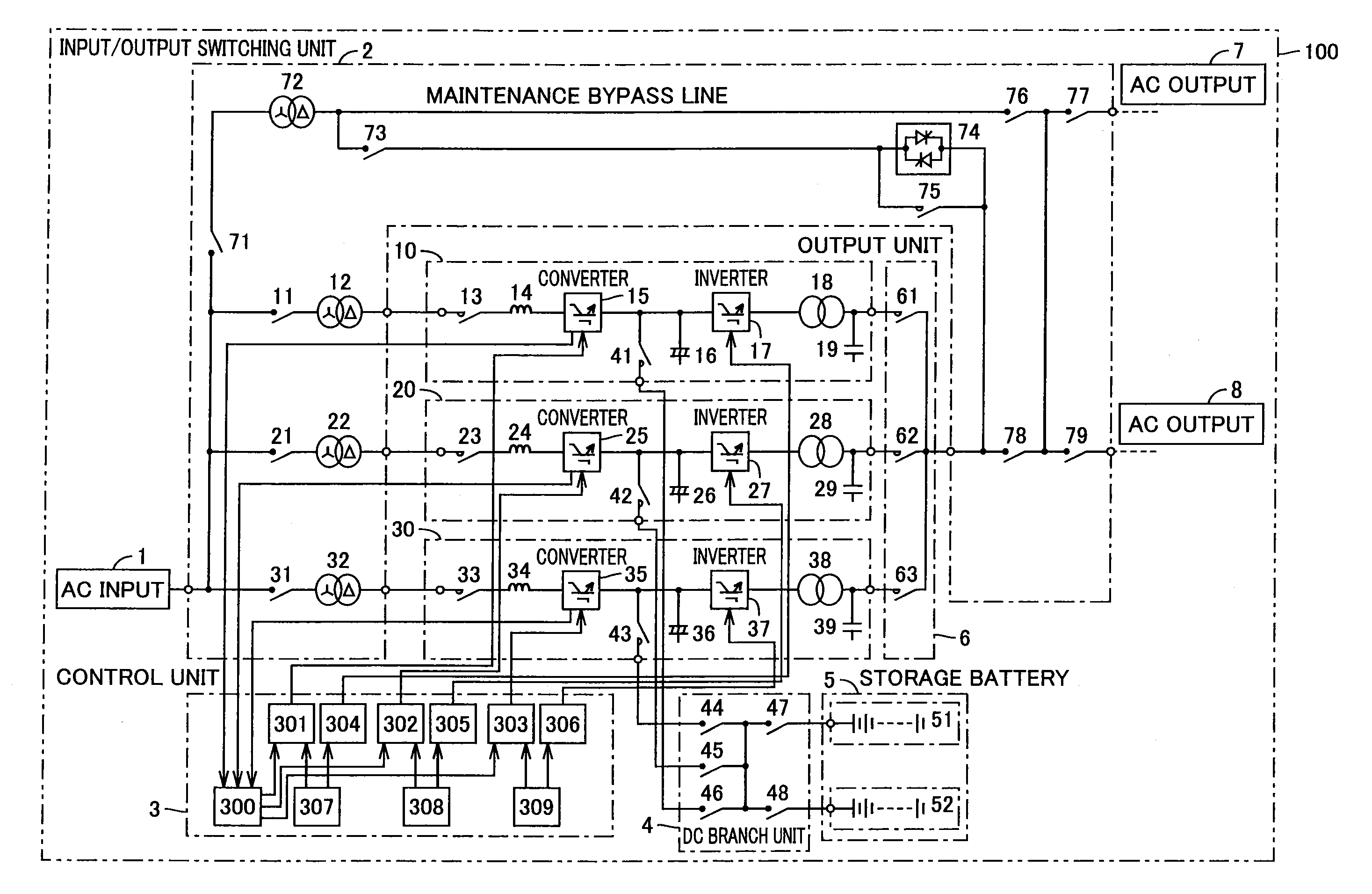
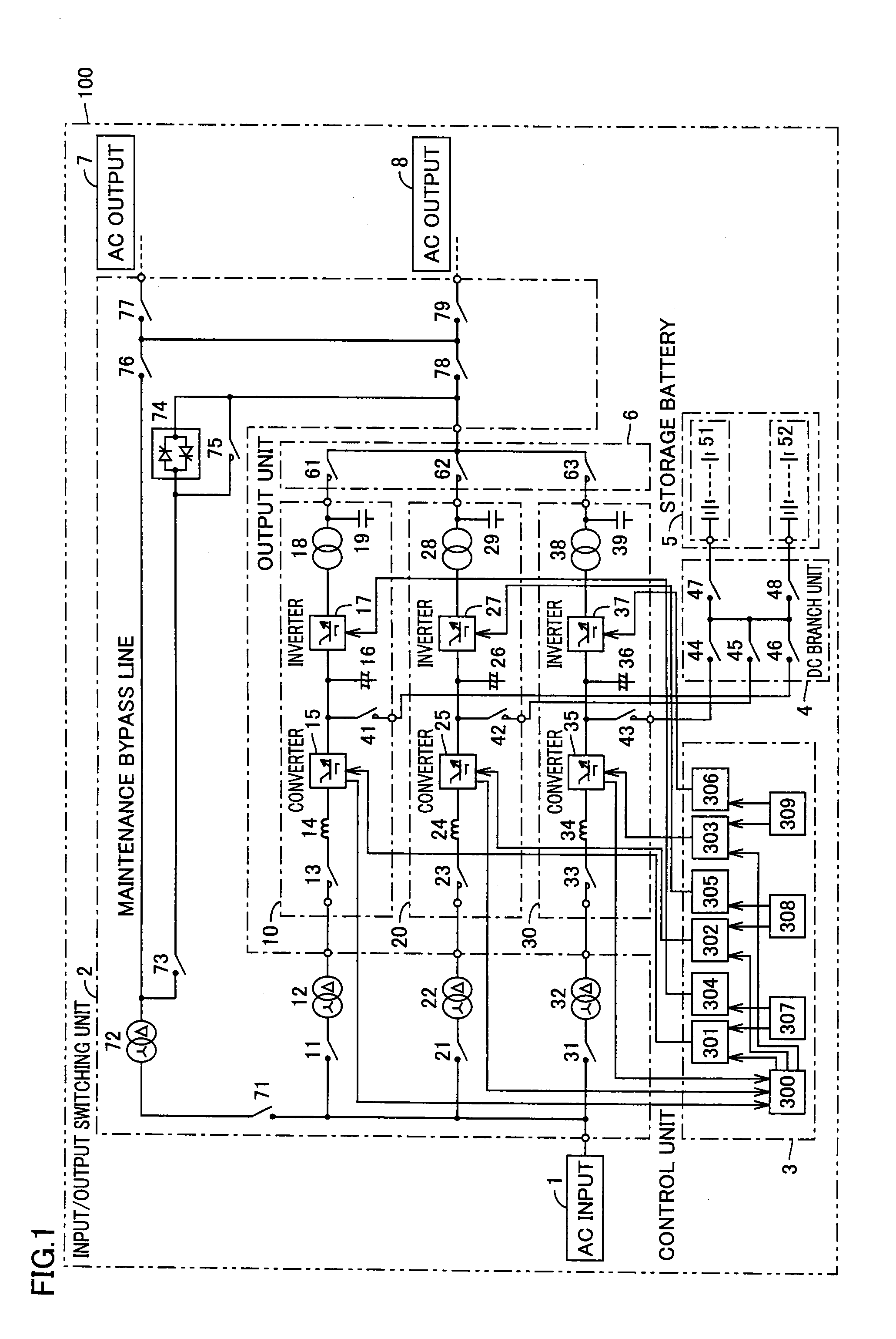
[0018]FIG. 1 is a schematic view showing a configuration of an uninterruptible power supply system in accordance with Embodiment 1 of the present invention. An uninterruptible power supply system 100 shown in FIG. 1 includes an AC input unit 1, an input / output switching unit 2, a control unit 3, a DC branch unit 4, a storage battery 5, an output unit 6, AC output units 7, 8, and uninterruptible power supply devices 10, 20, 30.

[0019]AC input unit 1 is connected to an AC power supply not shown to supply power to uninterruptible power supply devices 10, 20, 30. The AC power supply connected to AC input unit 1 is an AC power supply such as a commercial power supply or a private power generator.

[0020]AC output units 7, 8 are connected to a load not shown (such as a computer or communication equipment) to supply power from uninterruptible power supply devices 10, 20, 30 to the load. If the power to be supplied from uninterruptible power supply devices 10, 20, 30 is, for example, three-pha...

embodiment 2

[0053]An uninterruptible power supply system in accordance with Embodiment 2 of the present invention includes AC input unit 1, input / output switching unit 2, control unit 3, DC branch unit 4, storage battery 5, output unit 6, AC output units 7, 8, and uninterruptible power supply device 10, 20, 30, as with uninterruptible power supply system 100 in accordance with Embodiment 1. Thus, concerning the uninterruptible power supply system in accordance with Embodiment 2 of the present invention, components identical to those of uninterruptible power supply system 100 in accordance with Embodiment 1 will be designated by the same reference numerals, and a detailed description thereof will not be repeated.

[0054]Next, an operation of the uninterruptible power supply system in accordance with Embodiment 2 of the present invention will be described. FIG. 5 is a flowchart for illustrating the operation of the uninterruptible power supply system in accordance with Embodiment 2 of the present i...

embodiment 3

[0067]An uninterruptible power supply system in accordance with Embodiment 3 of the present invention includes AC input unit 1, input / output switching unit 2, control unit 3, DC branch unit 4, storage battery 5, output unit 6, AC output units 7, 8, and uninterruptible power supply device 10, 20, 30, as with uninterruptible power supply system 100 in accordance with Embodiment 1. Thus, concerning the uninterruptible power supply system in accordance with Embodiment 3 of the present invention, components identical to those of uninterruptible power supply system 100 in accordance with Embodiment 1 will be designated by the same reference numerals, and a detailed description thereof will not be repeated.

[0068]Next, an operation of the uninterruptible power supply system in accordance with Embodiment 3 of the present invention will be described. FIG. 6 is a flowchart for illustrating the operation of the uninterruptible power supply system in accordance with Embodiment 3 of the present i...


PUM


Abstract

An uninterruptible power supply system, including: a plurality of uninterruptible power supply devices which are connected in parallel with respect to a load, and switch between power supplies supplying power to the load depending on states of the power supplies; a control unit controlling an operation of switching between the power supplies by the uninterruptible power supply devices; and a storage battery connected to the plurality of uninterruptible power supply devices in common. The uninterruptible power supply device has a converter converting AC power of an AC power supply into DC power, a contactor switching between the DC power converted by the converter and DC power input from the storage battery, and an inverter inverting the DC power into AC power and supplying the power to the load. The control unit deactivates the converter which does not contribute to supplying a power amount required for the load, of a plurality of converters.

Description

TECHNICAL FIELD[0001]The present invention relates to an uninterruptible power supply system including a plurality of uninterruptible power supply devices connected in parallel, each uninterruptible power supply device converting alternating current (AC) power into direct current (DC) power and inverting the converted DC power or DC power of a storage battery into AC power to supply the power to a load.BACKGROUND ART[0002]An uninterruptible power supply system disclosed in Japanese Patent Laying-Open No. 2011-72068 (Patent Document 1) includes a plurality of uninterruptible power supply devices, a switching circuit switching to a bypass power supply with outage in case of failure of each uninterruptible power supply device, and a switch opening / closing an output of the switching circuit. The uninterruptible power supply system disclosed in Patent Document 1 is configured such that connection between the switching circuit and a load can be selected by the switch to select a configura...

Claims


Application Information

Patent Timeline
Patent Type & Authority Applications(United States)
IPC IPC(8): H02J9/06
CPCH02J9/061H02J3/46H02J9/062H02J2310/12H02J3/466Y02P80/14
Inventor TOYODA, MASARU
Owner TOSHIBA MITSUBISHI-ELECTRIC IND SYST CORP
Why Eureka
Try Eureka