Enclosed switchgear

a switchgear and closed technology, applied in the field of closed switchgear, can solve the problems of reducing the power loss between the contacts, and achieve the effects of reducing friction force, reducing the offset load on the surface of the contacts, and reducing the length of the members from the moving current-carrying shaft to the moving conta

Inactive Publication Date: 2005-08-09
MITSUBISHI ELECTRIC CORP
View PDF7 Cites 13 Cited by
  • Summary
  • Abstract
  • Description
  • Claims
  • Application Information

AI Technical Summary

Benefits of technology

[0020]In the enclosed type switchgear of above construction, only the moving current-carrying shaft and the moving contact are located on the vacuum valve side from the flexible contact pressure adjusting spring without any insulating rod. Therefore, length of the members from the moving current-carrying shaft to the moving contact is shortened as a whole. As a result, oscillation amount of the moving current-carrying shaft and of the moving contact of the vacuum valve is reduced, offset load on the surface of the contacts is reduced, and friction force at the portion on which the moving current-carrying shaft is supported is reduced.
[0021]In the enclosed type switchgear according to the invention, the insulating rod is fixed to the operating rod and the contact pressure adjusting spring is directly mounted on one end of the moving current-carrying shaft. Therefore, only the moving current-carrying shaft and the moving contact are located on the vacuum valve side from the contact pressure adjusting spring. Consequently, length of the members from the one end side of the moving current-carrying shaft to the moving contact is shortened as a whole. As a result, not only the switchgear is further miniaturized but also oscillation amount of the moving current-carrying shaft and the moving contact of the vacuum valve is reduced, and offset load on the surface of the contacts is reduced. Therefore, power loss between the contacts is decreased. Furthermore, friction force at the portion on which the moving current-carrying shaft is supported is reduced and, consequently, the operation mechanism part can be operated with small operation force, resulting in improvement of operation performance with ease.

Problems solved by technology

Therefore, power loss between the contacts is decreased.

Method used


Image

  • Enclosed switchgear
  • Enclosed switchgear
  • Enclosed switchgear

Examples


embodiment 1

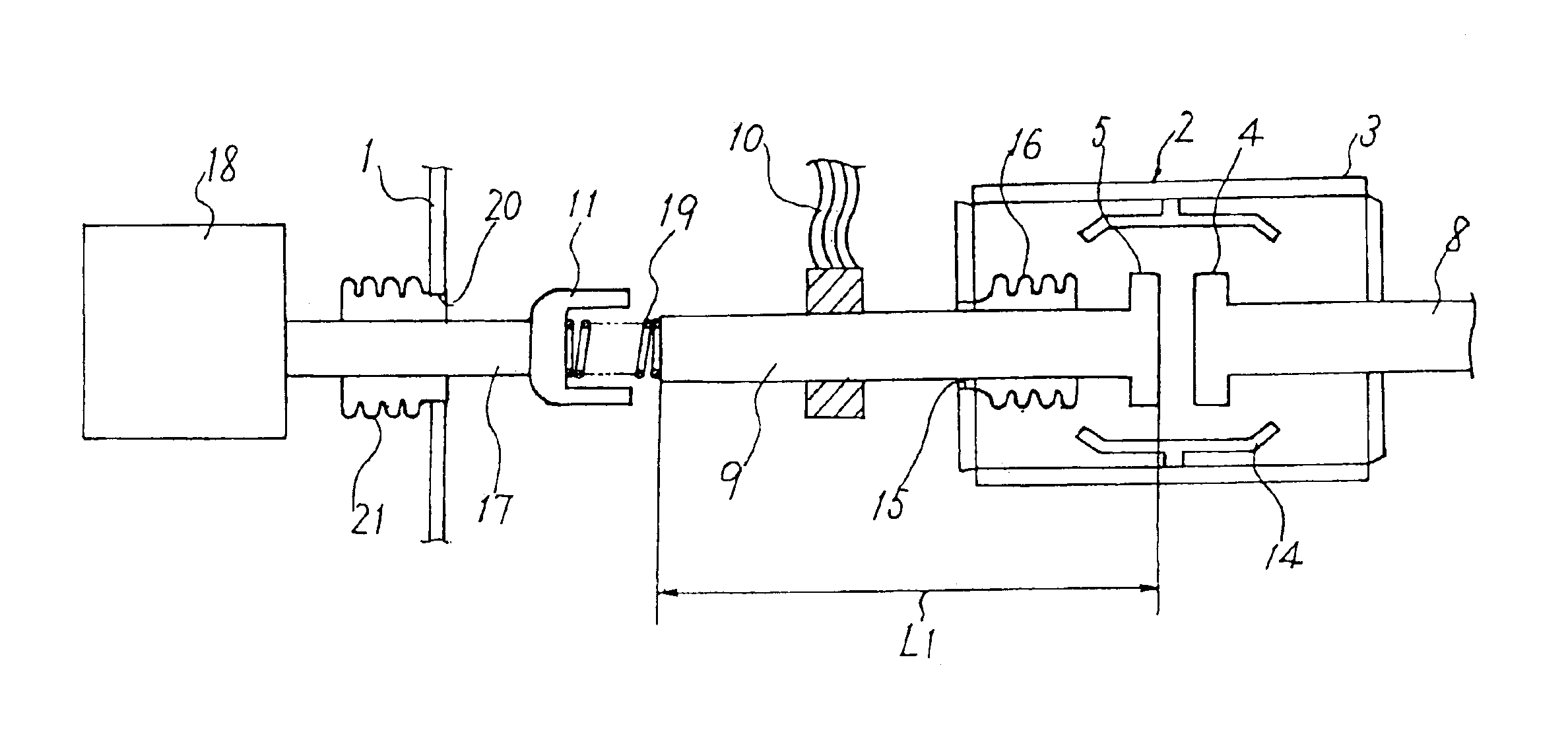
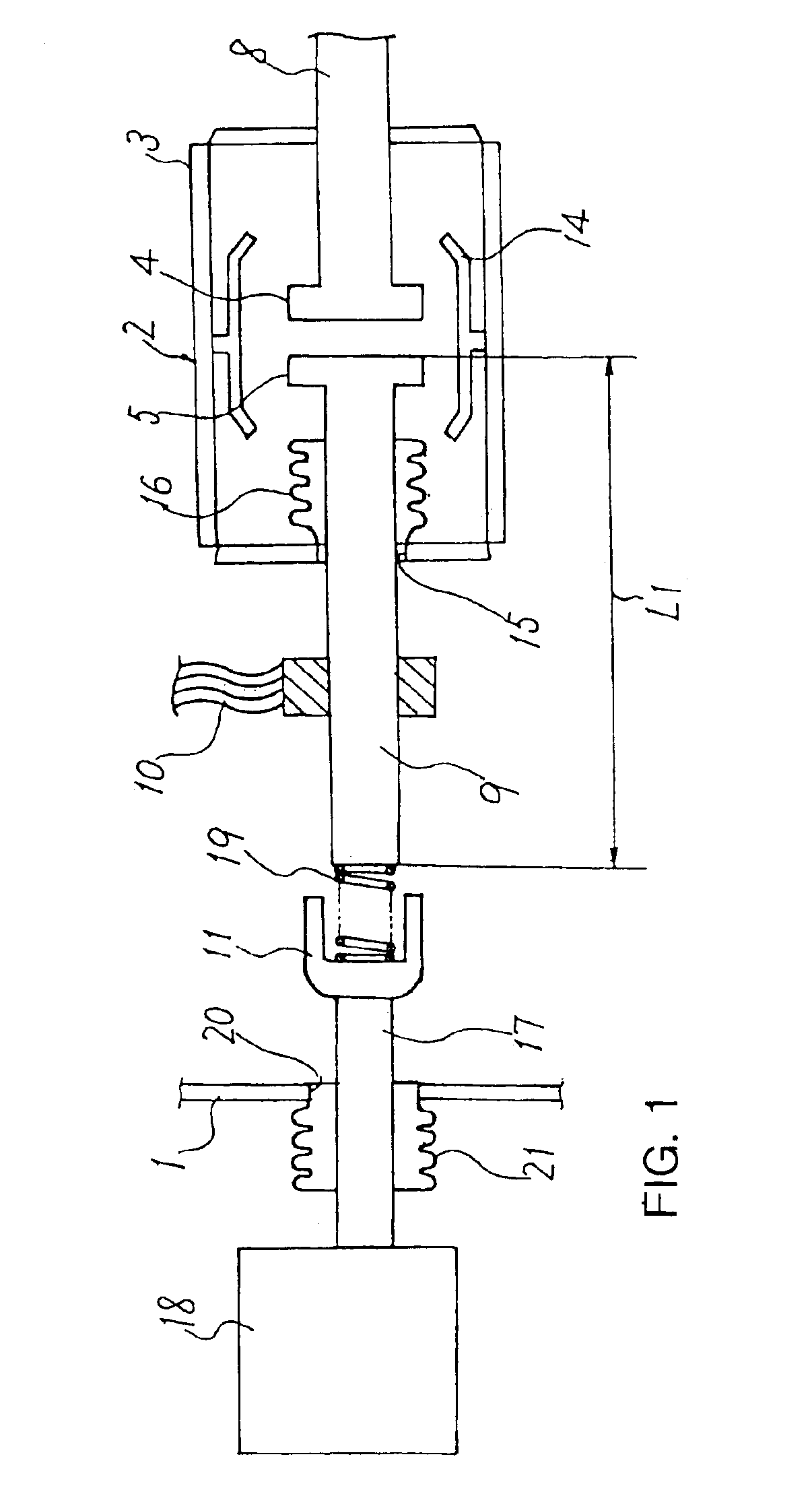
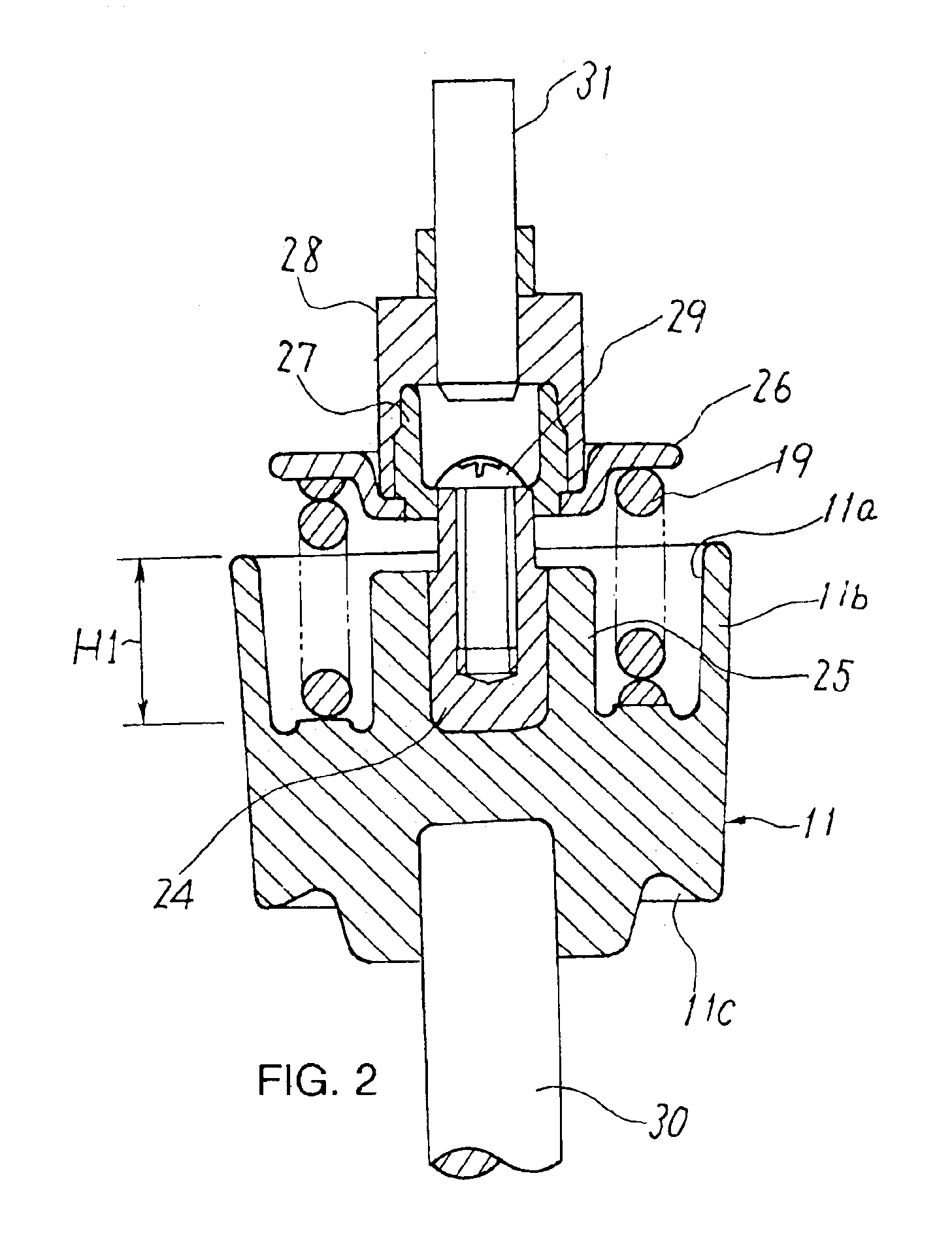
[0029]FIG. 1 is a schematic view showing a construction of enclosed type switchgear according to Embodiment 1 of the invention, and FIG. 2 is a sectional view taking out the portion in the vicinity of an insulating rod. The same reference numerals are designated to like components shown in FIG. 7.

[0030]The enclosed type switchgear according to this Embodiment 1 has a gas tank 1, and this gas tank 1 is filled with insulating gas. In this example, the gas tank 1 is filled with the insulating gas, which is an atmospheric air without treatment at an arbitrary pressure in a range from 0.1 to 0.30 MPa.abs.

[0031]A vacuum valve 2 is disposed in the gas tank 1 and fixed by a member not shown. This vacuum valve 2 is provided with a stationary switching contact 4 and a moving switching contact 5 forming a pair in a housing 3. One end of a stationary current-carrying shaft 8 is integrally provided with the stationary contact 4 of the vacuum valve 2, and one end side of a moving current-carrying...


PUM


Abstract

In a switchgear, oscillation of a moving current-carrying shaft and a moving contact of a vacuum valve is minimized, offset load on the contact surface is reduced, and friction the portion supporting the moving current-carrying shaft is reduced. A vacuum valve is disposed in a gas tank, one end of a moving current-carrying shaft integrally includes a moving contact of the vacuum valve, and a contact pressure adjusting spring is disposed on the other end of the moving current-carrying shaft. An operating rod extends through the gas tank, an operation mechanism is mounted on the operating rod outside the gas tank, an insulating rod is mounted inside the gas tank, and the contact pressure adjusting spring is joined to the insulating rod.

Description

BACKGROUND OF THE INVENTION[0001]1. Field of the Invention[0002]The present invention relates to an enclosed switchgear in which a vacuum valve provided with a pair of switching contacts and a moving mechanism part for moving the vacuum valve are disposed in a gas tank filled with an insulating gas.[0003]2. Description of the Related Art[0004]Hitherto, electric wiring has been connected and disconnected by a vacuum circuit breaker (as disclosed in, for example, the Japanese Patent Publication (unexamined) No. 1997-147700 (pages 1 to 5, FIGS. 1 to 7)). In this conventional vacuum circuit breaker disclosed in the Japanese Patent Publication (unexamined) No. 1997-147700, all members such as vacuum valve, insulating rod, contact pressure adjusting spring are left open to the atmospheric air.[0005]However, in such a case the all the members are left open (exposed) to the air, in order to secure a predetermined dielectric breakdown voltage, the entire switchgear becomes unavoidably large ...

Claims


Application Information

Patent Timeline
Patent Type & Authority Patents(United States)
IPC IPC(8): H01H33/66H01H33/666H01H33/02H01H33/56H02B13/02
CPCH01H33/666H01H33/565H01H2033/6667H01H33/6661E05C17/446E05Y2201/438E05Y2900/132
Inventor SATO, SHINJIKOYAMA, KENICHIARIOKA, MASAHIRO
Owner MITSUBISHI ELECTRIC CORP
Why Eureka
Try Eureka