Projection type video display apparatus
- Summary
- Abstract
- Description
- Claims
- Application Information
AI Technical Summary
Benefits of technology
Problems solved by technology
Method used
Image
Examples
first embodiment
[1] First Embodiment
[0056] Referring now to FIGS. 1 to 7, a first embodiment of the present invention will be described.
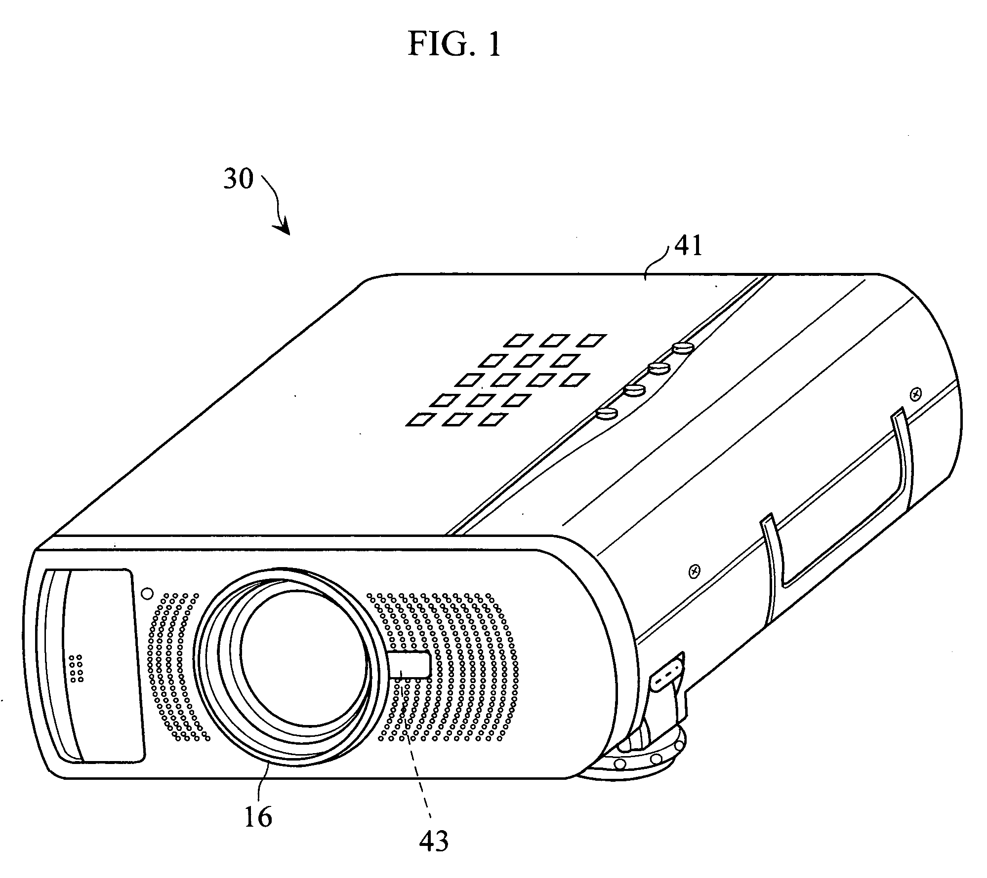
[0057]FIG. 1 is a diagram showing the appearance of a three-panel type liquid crystal projector 30.
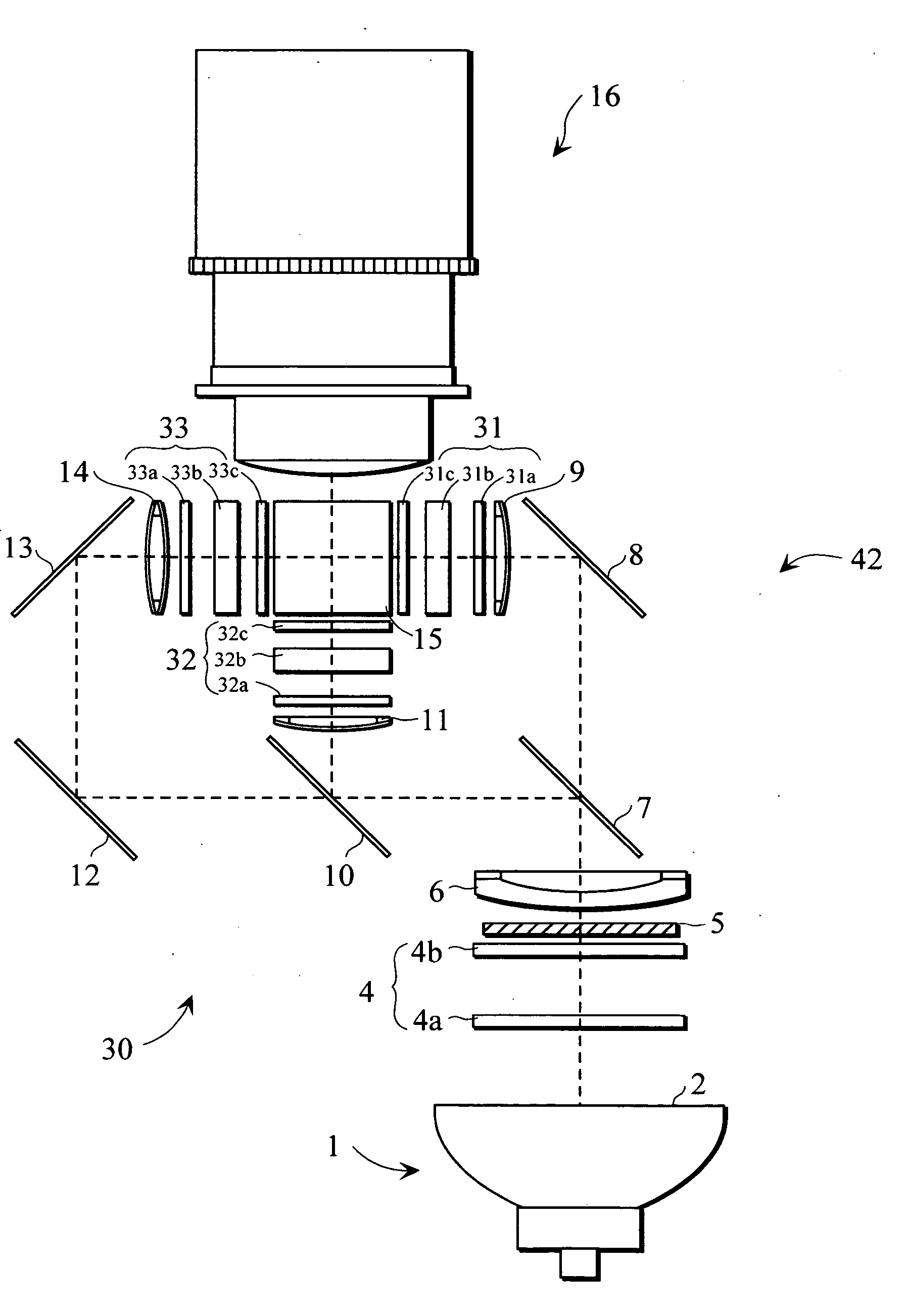
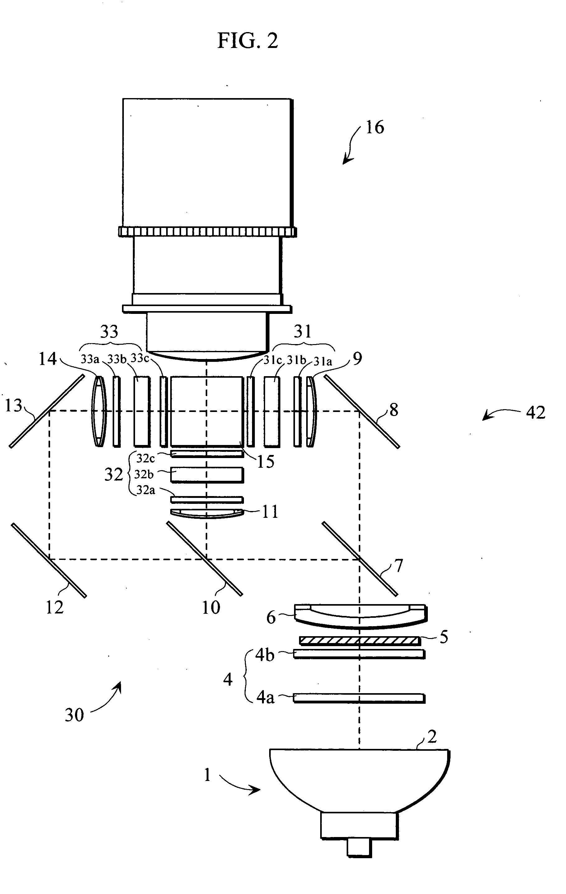
[0058] Within a main body case 41 in the liquid crystal projector 30, an optical system 42 (see FIG. 2) leading to a projection lens 16 (see FIGS. 1 and 2) from a light source 1 (see FIG. 2), described later, is arranged.
[0059]FIG. 2 is a diagram showing the configuration of the optical system 42 arranged within the main body case 41.
[0060] A light emitter in the light source 1 is composed of a ultrahigh pressure mercury lamp, a metal halide lamp, a xenon lamp, etc. Light irradiated from the light emitter in the light source 1 is emitted as parallel light by a parabolic reflector 2, and is introduced into an integrator lens 4.
[0061] The integrator lens 4 comprises a pair of lens groups (fly eye lenses) 4a and 4b, and so adapted that each of lens portions introduc...
second embodiment
[2] Second Embodiment
[0079] Referring now to FIGS. 8 to 11, a second embodiment of the present invention will be described.
[0080] The second embodiment is approximately the same as the first embodiment except that a projected video range is variable and a person detection range of a person detection sensor 43 is adjustable.
[0081]FIG. 8 illustrates the configuration of an optical system 42′ arranged within a main body case 41. In FIG. 8, the same components as those shown in FIG. 2 are assigned the same reference numerals and hence, the description thereof is not repeated.
[0082] Although the projection lens 16 is fixed in the first embodiment, a projection lens 16 in the second embodiment comprises a lens driving motor 22 for moving the projection lens 16 back and forth in order to enlarge or reduce a projected video.
[0083] As shown in FIGS. 10 and 11, the person detection sensor 43 is covered with a cylinder 50 held so as to be movable back and forth in the main body case 41. In...
third embodiment
[3] Third Embodiment
[0088] Referring now to FIGS. 12 to 23, a third embodiment of the present invention will be described.
[0089]FIG. 12 is a diagram showing the appearance of a three-panel type liquid crystal projector 130.
[0090] Within a main body case 141 in the liquid crystal projector 130, an optical system 142 leading to a projection lens 16 (see FIGS. 12 and 13) from a light source 12 (see FIG. 13), described later, is arranged.
[0091]FIG. 13 is a diagram showing the configuration of the optical system 142 arranged within the main body case 141. In FIG. 13, the same components as those shown in FIG. 2 are assigned the same reference numerals and hence, the description thereof is not repeated.
[0092] Also in the third embodiment, a projection lens 16 comprises a lens driving motor 22 for moving the projection lens 16 back and forth in order to enlarge or reduce a projected video, as in the second embodiment.
[0093] As shown in FIG. 12, person detection sensors 143a and 143b s...
PUM
 Abstract
Description
Claims
Application Information
 - R&D
- Intellectual Property
- Life Sciences
- Materials
- Tech Scout
- Unparalleled Data Quality
- Higher Quality Content
- 60% Fewer Hallucinations
Browse by: Latest US Patents, China's latest patents, Technical Efficacy Thesaurus, Application Domain, Technology Topic, Popular Technical Reports.
© 2025 PatSnap. All rights reserved.Legal|Privacy policy|Modern Slavery Act Transparency Statement|Sitemap|About US| Contact US: help@patsnap.com


