Reproducing apparatus and method, and recording and reproducing apparatus

a technology which is applied in the field of reproducing apparatus and reproducing apparatus, can solve the problems of difficult pll circuit to accurately reproduce a bit clock signal from the read-out signal, loss of bits of digital information along a time base, and loss of bit slips, etc., and achieve the effect of restricting the error rate to a small valu

Active Publication Date: 2006-02-09
JVC KENWOOD CORP A CORP OF JAPAN
View PDF1 Cites 4 Cited by
  • Summary
  • Abstract
  • Description
  • Claims
  • Application Information

AI Technical Summary

Benefits of technology

[0011] It is a first object of this invention to provide a reproducing apparatus which can prevent the error rate from being significantly increased by the occurrence of a bit slip.
[0012] It is a second object of this invention to provide a reproducing method which can prevent the error rate from being significantly increased by the occurrence of a bit slip.
[0013] It is a third object of this invention to provide a recording and reproducing apparatus which can prevent the error rate from being significantly increased by the occurrence of a bit slip.

Problems solved by technology

A very low signal level makes it difficult for a PLL circuit to accurately reproduce a bit clock signal from the read-out signal.
In such a case, the PLL circuit moves out of a state locked up with respect to the read-out signal, and hence a bit slip tends to occur.
Due to the bit slip, some bits of the digital information are lost along a time base.
Once bits have been lost due to a bit slip, even the viterbi decoding can not recover the lost bits.
Thus, the bit slip increases the error rate.
In the event that a bit slip occurs, the demodulation can not correctly recover some bits of the digital signal.

Method used


Image

  • Reproducing apparatus and method, and recording and reproducing apparatus
  • Reproducing apparatus and method, and recording and reproducing apparatus
  • Reproducing apparatus and method, and recording and reproducing apparatus

Examples


first embodiment

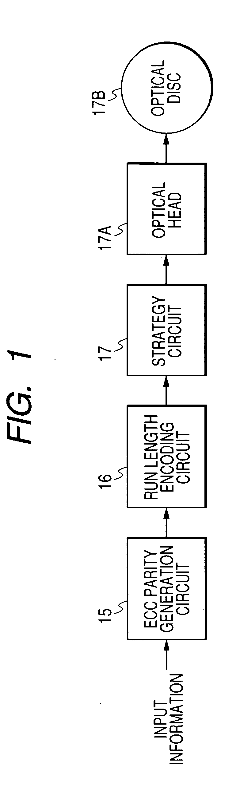
[0051]FIG. 1 shows the recording side of a recording and reproducing apparatus in a first embodiment of this invention. As shown in FIG. 1, the recording side of the apparatus includes an ECC parity generation circuit 15, a run length encoding circuit 16, a strategy circuit 17, and an optical head 17A which are sequentially connected in that order. The optical head 17A can act on an optical disc 17B.

[0052] The ECC parity generation circuit 15 receives input digital information to be recorded. The ECC parity generation circuit 15 produces parity signals (ECC parity signals) in response to the input digital information. The parity signals include, for example, RS (Reed-Solomon) code signals and LDPC (low-density parity-check code) signals. The ECC parity generation circuit 15 adds the parity signals (the ECC parity signals) to the input digital information to get parity-added digital information. The ECC parity generation circuit 15 outputs the parity-added digital information to the...

second embodiment

[0095] The recording side of a recording and reproducing apparatus in a second embodiment of this invention is the same as that in the first embodiment of this invention.

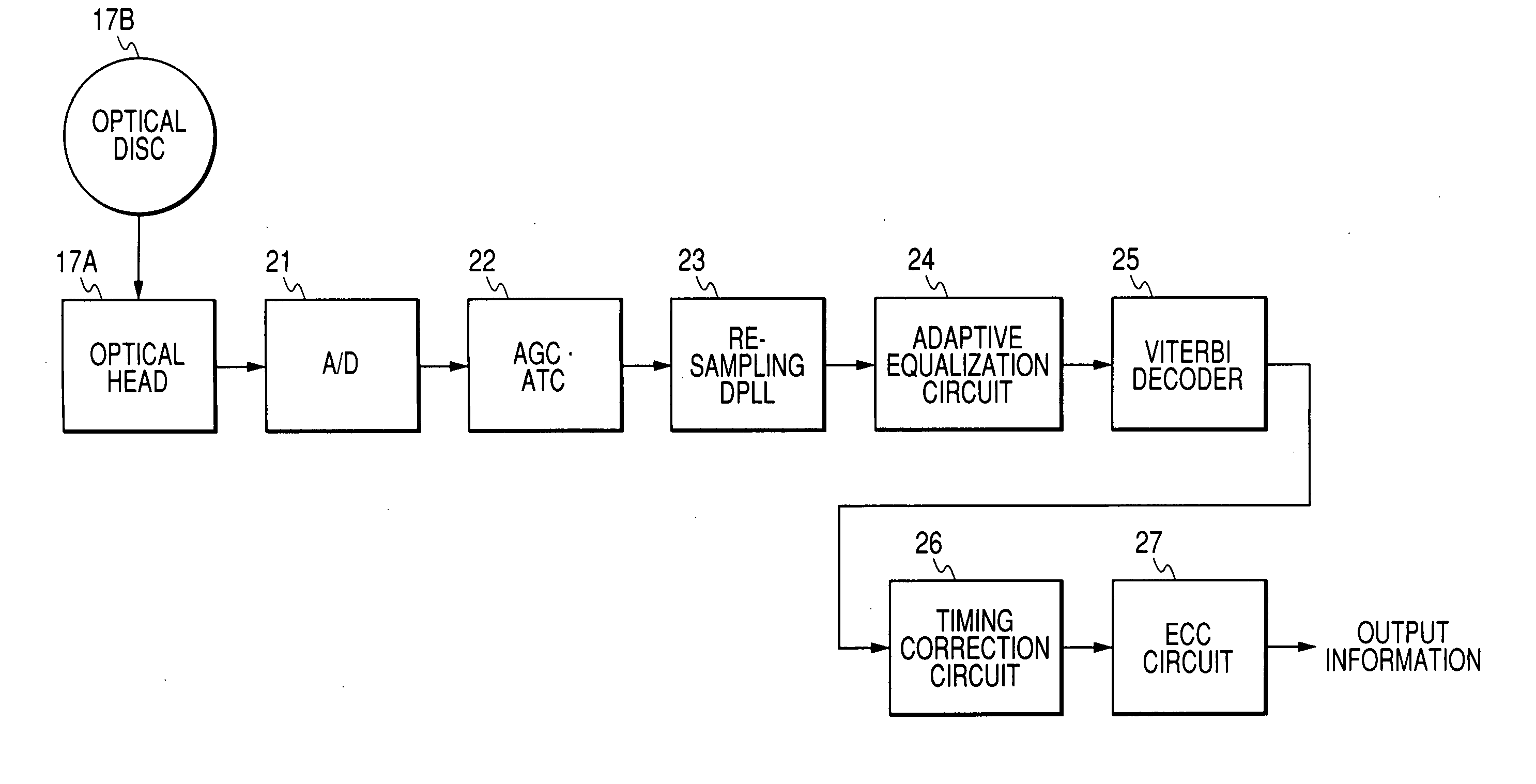
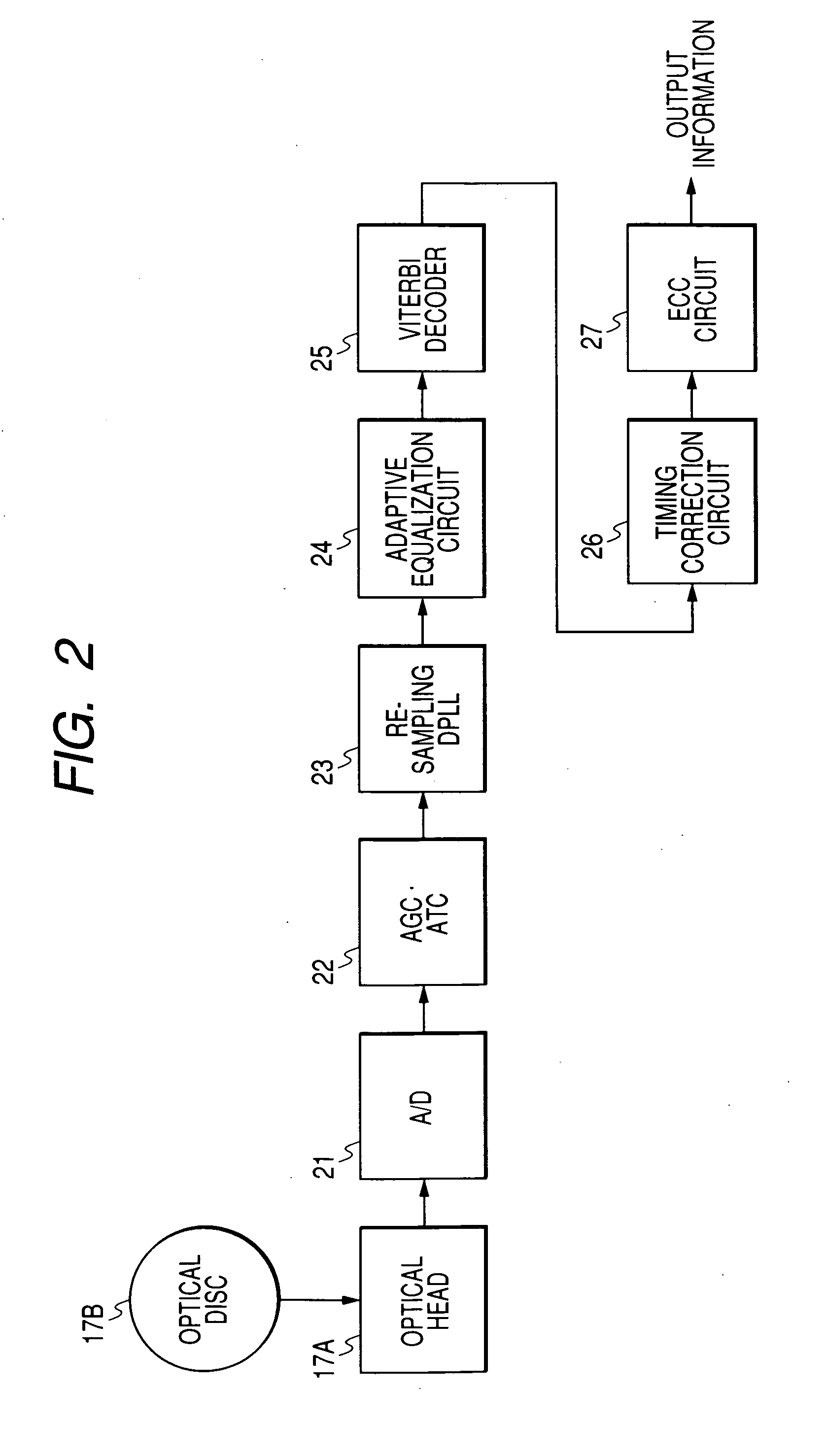
[0096]FIG. 11 shows the reproducing side of the apparatus in the second embodiment of this invention. The reproducing side of the apparatus in FIG. 11 is similar to that in FIG. 2 except that a timing correction circuit 30 replaces the timing correction circuit 26 (see FIG. 2).

[0097] The timing correction circuit 30 receives the viterbi-decoded signal (the output signal of the viterbi decoder 25). The timing correction circuit 30 subjects the viterbi-decoded signal to run length decoding and timing correction. The timing correction circuit 30 outputs the resultant signal to the ECC circuit 27 as a second decoding-resultant signal.

[0098] The timing correction circuit 30 is designed to retrieve correct bit positions even in the case where a bit slip occurs so that on-signal bit positions are shifted from normal one...

third embodiment

[0133]FIG. 18 shows the recording side of a recording and reproducing apparatus in a third embodiment of this invention. The recording side in FIG. 18 is similar to that in FIG. 1 except that an ECC parity generation circuit 18 is interposed between the run length encoding circuit 16 and the strategy circuit 17.

[0134] The ECC parity generation circuit 18 receives the sequence of words of the run length limited code from the run length encoding circuit 16. The ECC parity generation circuit 18 produces parity signals (ECC parity signals) in response to the sequence of words of the run length limited code. The parity signals include, for example, RS code signals and LDPC signals. The ECC parity generation circuit 18 adds the parity signals (the ECC parity signals) to the sequence of words of the run length limited code to get a parity-added sequence of words of the run length limited code. The ECC parity generation circuit 18 outputs the parity-added sequence of words of the run lengt...


PUM

PropertyMeasurementUnit
run lengthaaaaaaaaaa
run-lengthaaaaaaaaaa
lengthaaaaaaaaaa

Abstract

A signal of a run-length-limited code is read out from a recording medium. The read-out signal is converted into a reproduced digital signal. A decoder subjects the reproduced digital signal to first decoding different from run length decoding to get a first decoded signal. Information bit streams are generated from the first decoded signal. The information bit streams are different in timing by 1-bit-correpsonding intervals. Run length decoders subject the information bit streams to run length decoding to get run-length-decoded bit streams respectively. Each of the run-length-decoded bit streams undergoes one of error correction and error detection. A decision is made as to which of the run-length-decoded bit streams is the smallest in error number on the basis of results of the one of error correction and error detection. The run-length-decoded bit stream being the smallest in error number is selected and outputted as a likeliest information bit stream.

Description

BACKGROUND OF THE INVENTION [0001] 1. Field of the Invention [0002] This invention relates to a method and an apparatus for reproducing a signal of a run-length-limited code from a recording medium such as an optical disc. In addition, this invention relates to an apparatus for recording and reproducing a signal of a run-length-limited code on and from a recording medium such as an optical disc. [0003] 2. Description of the Related Art [0004] Japanese patent application publication number 10-106161 / 1998 discloses an optical information reproducing apparatus based on a PRML (partial response maximum likelihood) system. In the apparatus of Japanese application 10-106161, information of a run-length-limited code is reproduced from an optical disc through a reproducing section, and a transversal filter subjects the reproduced waveform to partial-response equalization depending on tap coefficients. An example of the partial-response equalization is PR(1, X, X, 1) equalization. The output...

Claims


Application Information

Patent Timeline
Patent Type & Authority Applications(United States)
IPC IPC(8): G11B20/10
CPCG11B20/1426G11B20/1833G11B2220/2541G11B2020/1288G11B2020/1863G11B2020/1272
Inventor TONAMI, JUNICHIROFUJIWARA, YUUKI
Owner JVC KENWOOD CORP A CORP OF JAPAN
Why Eureka
Try Eureka