Device for holding linear guide rail

a technology of guiding rail and guide rail, which is applied in the direction of bearings, shafts and bearings, bearings, etc., can solve the problems of inconvenient holding and incorrect engagement of guide rail r by reference faces l

Inactive Publication Date: 2006-02-09
INFOM
View PDF2 Cites 14 Cited by
  • Summary
  • Abstract
  • Description
  • Claims
  • Application Information

AI Technical Summary

Benefits of technology

[0011] It is, therefore, an object of the present invention to provide a holding device which can sol

Problems solved by technology

When such a mounting failure occurs, there is a possibility that the guide rail R is

Method used


Image

  • Device for holding linear guide rail
  • Device for holding linear guide rail
  • Device for holding linear guide rail

Examples


Embodiment Construction

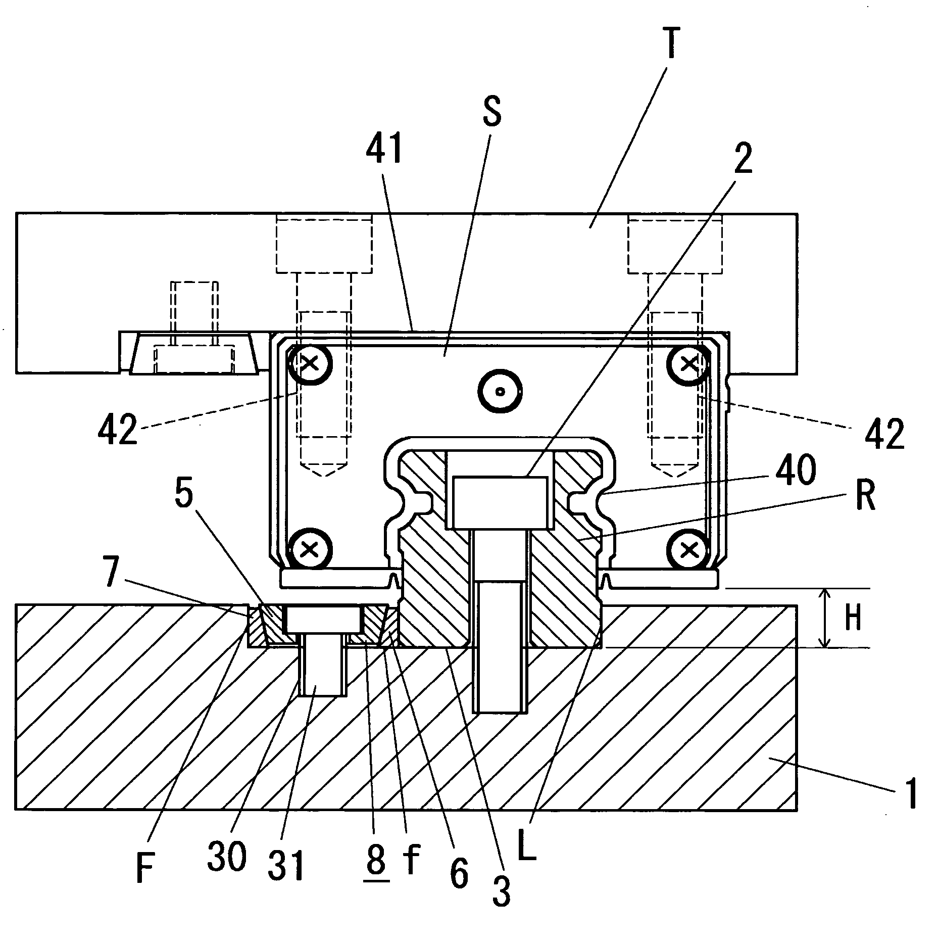
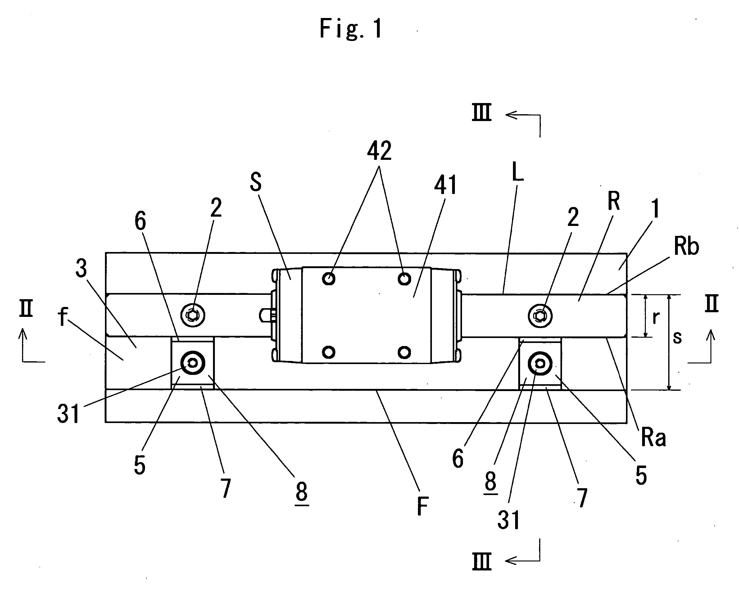
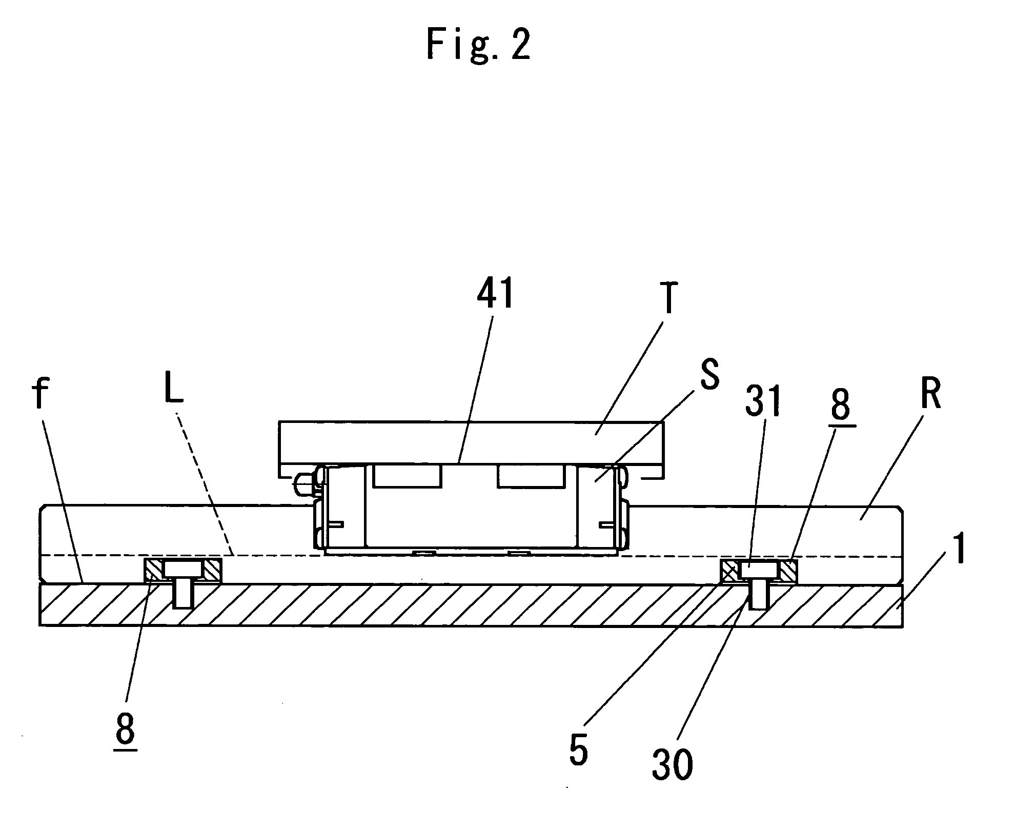
[0044] Description will be hereinafter made of the embodiments of the present invention with reference to accompanying drawings. Referring first to FIG. 1 to FIG. 3, designated as 1 is a base on which a linear guide rail R having a first side Ra and a second side Rb is adapted to be fixedly secured by bolts 2. A linear slider S for mounting a machine tool T or the like thereon is mounted on the linear guide rail R for linear sliding movement along the linear guide rail R. The linear slider S has a fitting groove 40 shaped to match the cross-sectional shape of the linear guide rail R and a mounting face 41 for mounting the machine tool T thereon. Fitting screw holes 42 for fixing the machine tool T are formed vertically in the mounting face 41 along opposite edges thereof (see FIG. 3).

[0045] When the securing bolts 2 are not tightened, the linear guide rail R can be slightly moved with respect to the securing bolts 2. Thus, in the state where the securing bolts 2 are in a loosened s...


PUM


Abstract

A device for holding a linear guide rail R along a linearly extending vertical reference surface L formed on an installation surface f provided with a vertical counter surface F, including a pressing plate 5, and first and second pressure contacting piece 7 and 6. The pressing plate 5 has a central fitting hole 11 and inwardly downwardly tapered side surfaces 10b, 10a which are face-to-face engageable with tapered side faces 15, 14 of the first and second pieces 7 and 6. When a screw 31 inserted through the fitting hole 11 of the pressing plate is tightened into the female thread hole 30 of the installation surface f, the pressing plate is moved downward so that the first and second pieces 7 and 6 are moved to press the guide rail R positioned on the installation surface f between the reference surface L and the second piece 6 against the reference surface L.

Description

BACKGROUND OF THE INVENTION [0001] 1. Field of the Invention [0002] This invention relates to a holding device for a linear guide rail applied to a machining center or a lathe for slidably guiding a machine tool or the like in the longitudinal direction thereof. [0003] 2. Description of Prior Art [0004] A linear guide rail R for slidably guiding a machine or the like in the longitudinal direction thereof as shown in FIG. 14 is widely used as a machine element. When the linear guide R is installed, it is positioned in contact with a vertical reference face L extending vertically from an installation surface f, and a plurality of bolts j are threaded into corresponding threaded holes i formed in the installation surface f through holes h formed through the guide rail R at specified intervals and having a large diameter. [0005] In such a configuration, however, even when the vertical reference face L has an even and uniform surface, the guide rail R may not snugly fit against the refer...

Claims


Application Information

Patent Timeline
IPC IPC(8): F16C29/06
CPCF16B3/06F16B5/12F16C29/06F16C29/004F16C29/005F16B43/00
Inventor ITO, TAKAYOSHI
Owner INFOM
Why Eureka
Try Eureka