
System and method for providing strain relief for medical device leads

a technology of medical devices and leads, applied in the field of providing strain relief, can solve the problems of fig. 1 providing opportunity for errors during installation, low cost and effective strain relief, etc., and achieve the effect of simple and relatively inexpensive lead assembly, simplified installation of lead assembly into medical device, and convenient visual verification for users

Inactive Publication Date: 2006-02-09
ADVANCED NEUROMODULATION SYST INC
View PDF8 Cites 19 Cited by
  • Summary
  • Abstract
  • Description
  • Claims
  • Application Information

AI Technical Summary

Benefits of technology

[0009] The strain relief portion of a preferred embodiment header assembly is adapted to facilitate a user visually verifying when a lead has been fully inserted into the header. For example, at least a portion of the strain relief portion may be substantially transparent for visually verifying when a particular portion of the lead is in juxtaposition therewith. Structure, such as a band or ring, is provided upon embodiments of the strain relief portion in order to provide a readily identifiable visual aid for determining when a lead is fully inserted.
[0010] It should be appreciated that an integral strain relief portion as provided according to embodiments of the present invention provides advantages in that there is no separate part to manufacture, inventory, track, include into a kit or other product package, etcetera. Moreover, manufacturing such a strain relief portion as a part of a header assembly allows a simple and relatively inexpensive lead assembly to be used, as compared to a lead assembly having an integrated strain relief as in the prior art, although installation of the lead assembly into the medical device is simplified.

Problems solved by technology

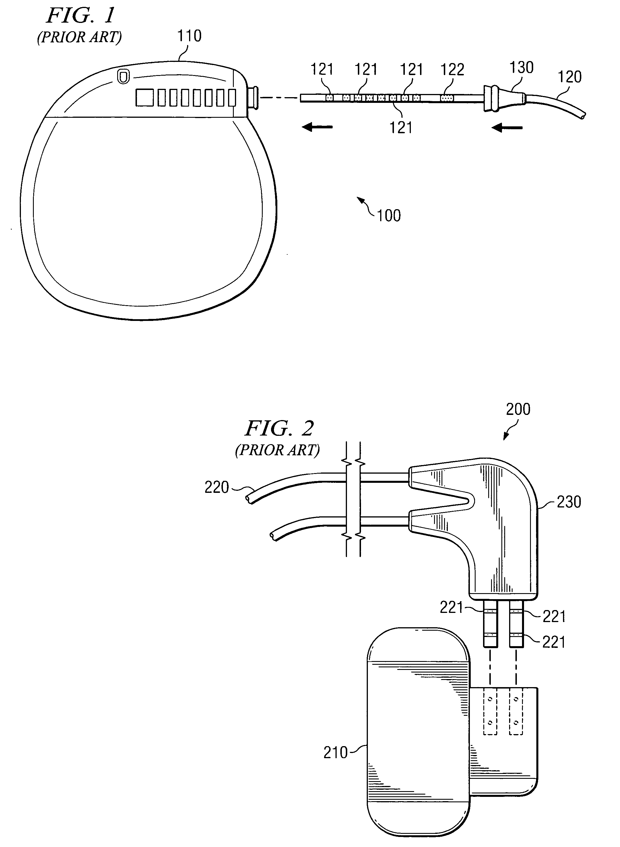
Although providing a relatively low cost and effective strain relief, the configuration of FIG. 1 provides opportunity for error during installation.
Although providing strain relief which is very simple to implement in the field, the configuration of FIG. 2 requires complicated and costly manufacturing techniques and results in a large lead assembly and pulse generator lead interface.

Method used


Image

  • System and method for providing strain relief for medical device leads
  • System and method for providing strain relief for medical device leads
  • System and method for providing strain relief for medical device leads

Examples


Embodiment Construction

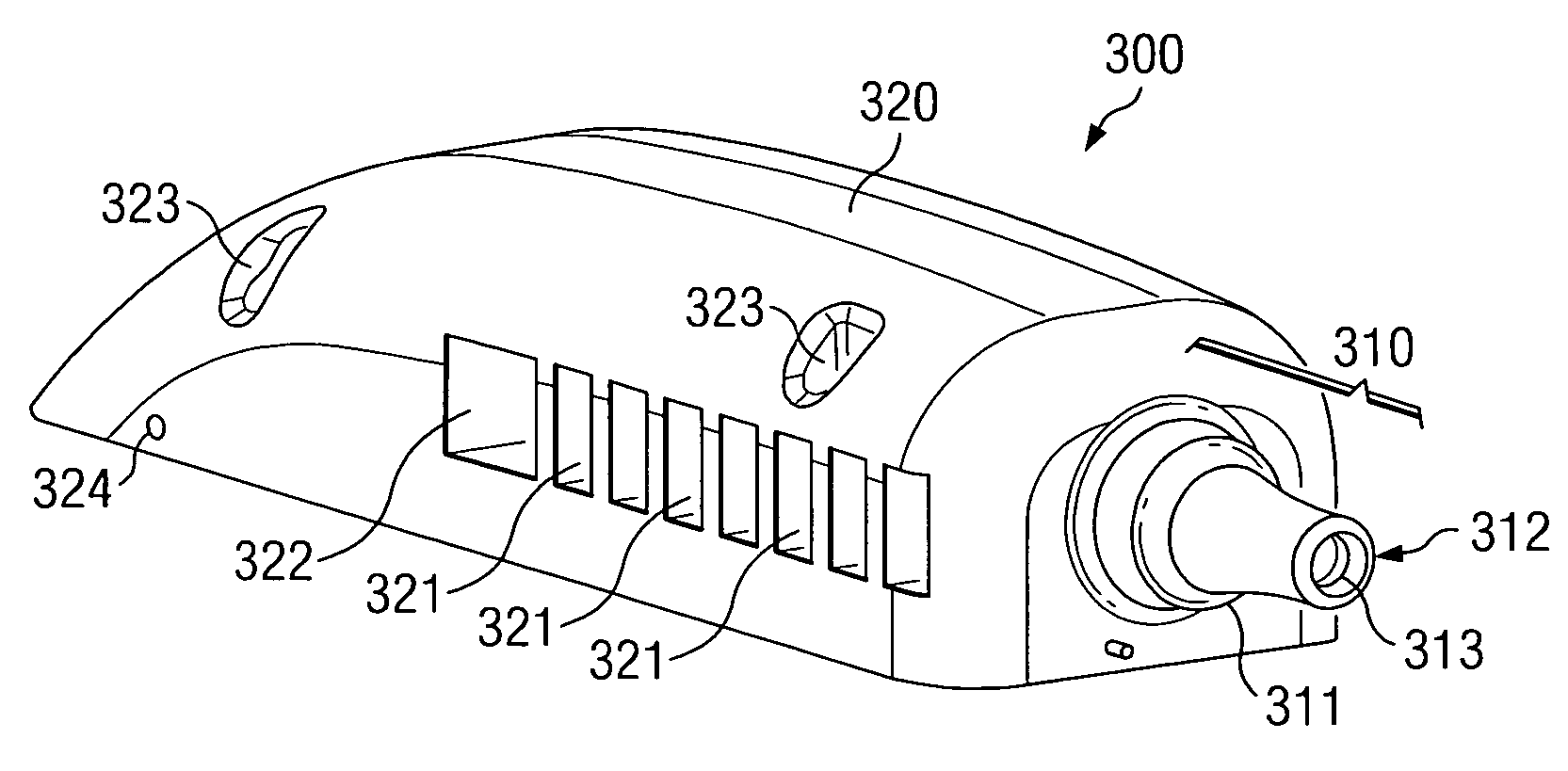
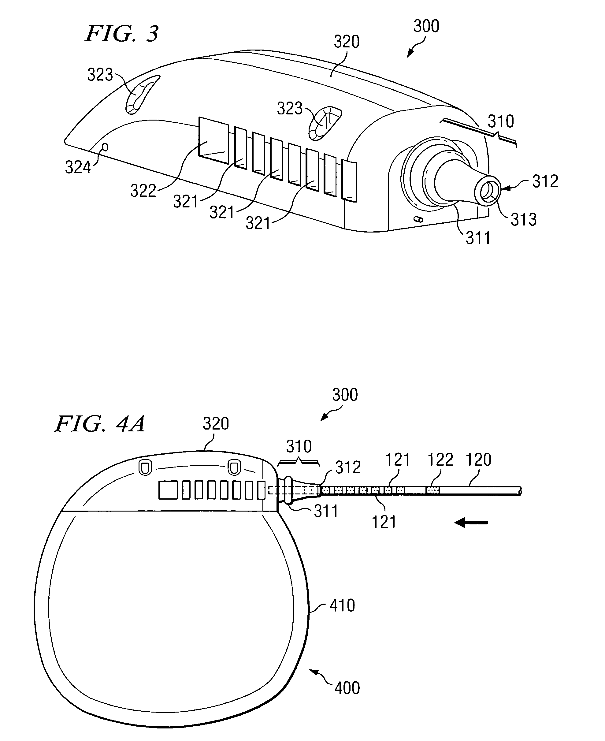
[0019] Directing attention to FIG. 3, a medical device header assembly adapted according to an embodiment of the present invention is shown as header assembly 300. Header assembly 300 of the illustrated embodiment includes strain relief portion 310 and body portion 320. Strain relief portion 310 and body portion 320 of preferred embodiments, although providing separate and distinct functional aspects, are integrated as a single header assembly unit. Such an embodiment provides an inexpensive and relatively simple to manufacture solution, as well as eliminating costs and errors associated with collecting components into a kit or assembly, assembling components, etcetera.

[0020] Header assembly 300, and thus strain relief portion 310 and body portion 320, of a preferred embodiment is comprised of a resilient, biocompatible, material, such as silicone rubber (e.g., SILASTIC available from Dow Coming Corporation, Midland Michigan). Accordingly, header assembly 300 may be injection molde...


PUM


Abstract

Disclosed are systems and methods which provide a header assembly for interfacing a medical device with a lead, wherein the header assembly includes a strain relief portion integral thereto. The strain relief portion may be adapted to facilitate a user visually verifying when a lead has been fully inserted into the header. Structure, such as a band or ring, may be provided upon the strain relief portion in order to provide a readily identifiable visual aid for determining when a lead is fully inserted.

Description

RELATED APPLICATIONS [0001] Priority is hereby claimed to co-pending and commonly assigned U.S. provisional patent application Ser. No. 60 / 599,953 entitled “System and Method for Providing Strain Relief for Medical Device Leads,” filed Aug. 9, 2004, the disclosure of which is hereby incorporated herein by reference. The present application is related to co-pending and commonly assigned U.S. patent applications Ser. No. 29 / 206,769 entitled “Design for Stimulator Lead Adapter,” filed Jun. 3, 2004, and Ser. No. 29 / 204,866 entitled “Stimulator Lead Adapter,” filed May 5, 2004, the disclosures of which are hereby incorporated herein by reference.TECHNICAL FIELD [0002] The present invention relates generally to medical devices having leads associated therewith and, more particularly, to providing strain relief with respect to the foregoing leads. BACKGROUND OF THE INVENTION [0003] Numerous medical devices have been developed and utilized for providing pain management therapy to patents. F...

Claims


Application Information

Patent Timeline
Patent Type & Authority Applications(United States)
IPC IPC(8): H01R3/00
CPCA61N1/3752
Inventor JONES, ROBERT E.CULLEN, PATRICK M.DAGLOW, TERRY D.
Owner ADVANCED NEUROMODULATION SYST INC
Learn More