
Demountable exercise device

a technology of exercise device and mounting plate, which is applied in the direction of muscle exercise device, resistance force resistor, sport apparatus, etc., can solve the problems of limited exercise scope, limited portability, and not intended for quick and convenient disassembly, etc., to achieve maximum durability and reliability, easy transportation and assembling, and convenient assembly for use and disassembly

Inactive Publication Date: 2006-02-09
UDWIN ELIEZER
View PDF6 Cites 12 Cited by
  • Summary
  • Abstract
  • Description
  • Claims
  • Application Information

AI Technical Summary

Benefits of technology

"The present invention is a lightweight, demountable, multi-purpose exercise device that can be easily assembled and disassembled for convenience. It can be used for a wide variety of exercises and is durable and reliable. The exercise device includes telescopic members, handle elements, resilient means, and elongate flexible means for attachment between the telescopic members to prevent accidental disassembly. The exercise device also includes a retractable spool member and elongate flexible members that can be uncoiled in response to a pulling force greater than a resistance force. The invention provides a versatile and easy-to-use exercise device that can be conveniently packed and transported while still being effective and reliable."

Problems solved by technology

However, these are generally limited in the scope of exercises which can be performed by their use.
The above-mentioned device, while providing features for performing multiple exercises, is portable only to a limited extent.
Being, of necessity, a lengthy device having a fixed assembly of its component parts, it is not intended for quick and convenient disassembly to facilitate compact packing and transporting, and for quick subsequent re-assembly for use.

Method used


Image

  • Demountable exercise device
  • Demountable exercise device
  • Demountable exercise device

Examples


Embodiment Construction

[0021] At present, many people expend a substantial amount of time traveling, be it for business or pleasure. While not traveling, those who wish to do physical exercises have the opportunity to visit their local gymnasium or sports facility. While traveling, however, this is not such a simple matter. There is therefore a need for facilitating an exercise program for travelers, utilizing a lightweight, portable, and simple exercise device. The present invention seeks to provide such a device, which is easily assembled, from a few component parts, easily disassembled and is very compact and portable and may, for example, be packed into a shoe-box sized container or bag. Furthermore, it is usable for a wide range of exercises for the arms, legs, chest, back, stomach, and posterior.

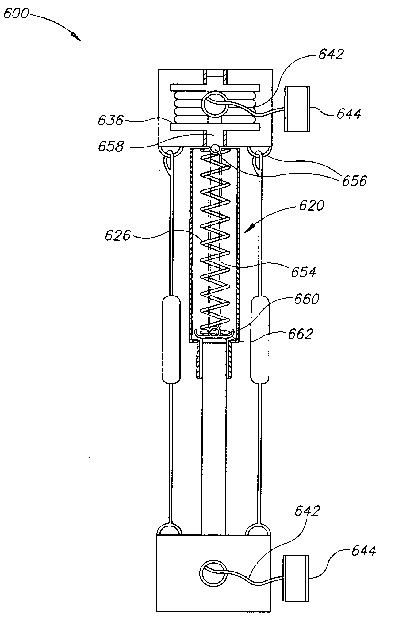
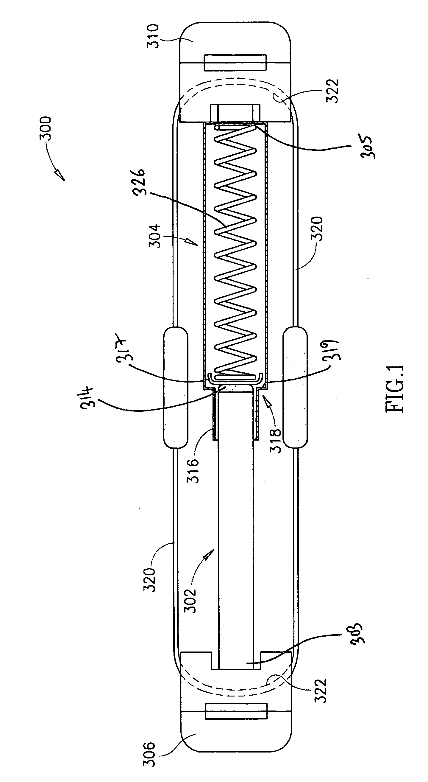
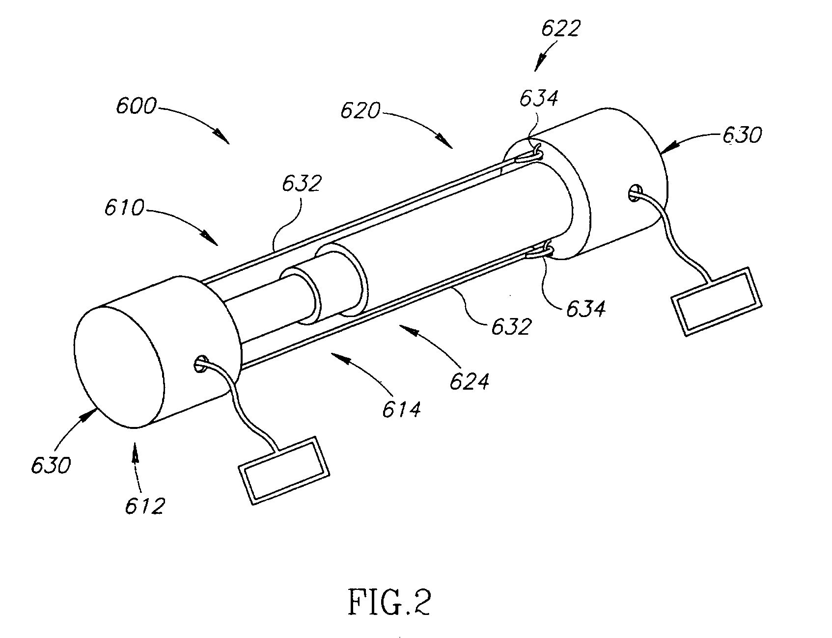
[0022] Referring now to FIG. 1, there is provided a demountable exercise device referenced generally 300, which includes first and second, coaxially arranged, mutually engageable telescopic members, respect...


PUM


Abstract

A demountable multi-purpose exercise device includes first and second elongate, mutually engageable telescopic members, each having first and second end portions, wherein when the elongate members are mutually engaged the first end portions are mutually distal and the second end portions are mutually slidably engaged, the second end portion of the second telescopic member being formed as a narrowed, tubular guide portion to facilitate the axial, telescopic sliding of the first telescopic member therewith; a pair of handle elements disposed at each first end portion of the first and second telescopic elongate members; compressible resilient member disposed between the first and second elongate, telescopic members, to permit mutual contraction in response to a compressive, axial force of at least a predetermined magnitude applied thereto via the first ends thereof; and elongate flexible elements for attachment between the first ends of the first and second telescopic members, for preventing inadvertent disassembly.

Description

CROSS REFERENCE TO RELATED APPLICATIONS [0001] The present application is a continuation-in-part application of International Application No. PCT / IL 2004 / 000089, filed on Jan. 29, 2004, and entitled Demountable Multi-Purpose Exercise Device; which is a continuation-in-part application of U.S. Ser. No. 10 / 453,997, filed on Jun. 4, 2003, publication number 2004 / 01527571, and entitled Demountable Multi-Purpose Exercise Device; which is a continuation-in-part application of U.S. Ser. No. 10 / 654,103, filed on Jan. 30, 2003, publication number 2004 / 0152570, and entitled Demountable Multi-Purpose Exercise Device; all in the name of the present Inventor. The contents of these applications are incorporated herein, by reference.FIELD OF THE INVENTION [0002] The present invention relates, generally to an exercise device and, more specifically, to an exercise device, which can be easily disassembled. BACKGROUND OF THE INVENTION [0003] It is known in the art to provide exercise devices to facili...

Claims


Application Information

Patent Timeline
Patent Type & Authority Applications(United States)
IPC IPC(8): A63B21/02A63B21/05A63B21/00A63B21/055A63B23/12
CPCA63B21/00043A63B21/00185A63B21/023A63B21/0428A63B21/05A63B21/055A63B2208/0238A63B21/1426A63B21/1488A63B21/153A63B23/03508A63B23/12A63B2071/027A63B21/0552A63B21/4013A63B21/4045A63B23/1209A63B23/03533A63B23/03541A63B23/0355A63B21/4043A63B21/4035
Inventor UDWIN, ELIEZER
Owner UDWIN ELIEZER
Learn More