

Anesthesia intubating forceps
- Summary
- Abstract
- Description
- Claims
- Application Information
AI Technical Summary
Benefits of technology
Problems solved by technology
Method used
Image

Examples
Embodiment Construction
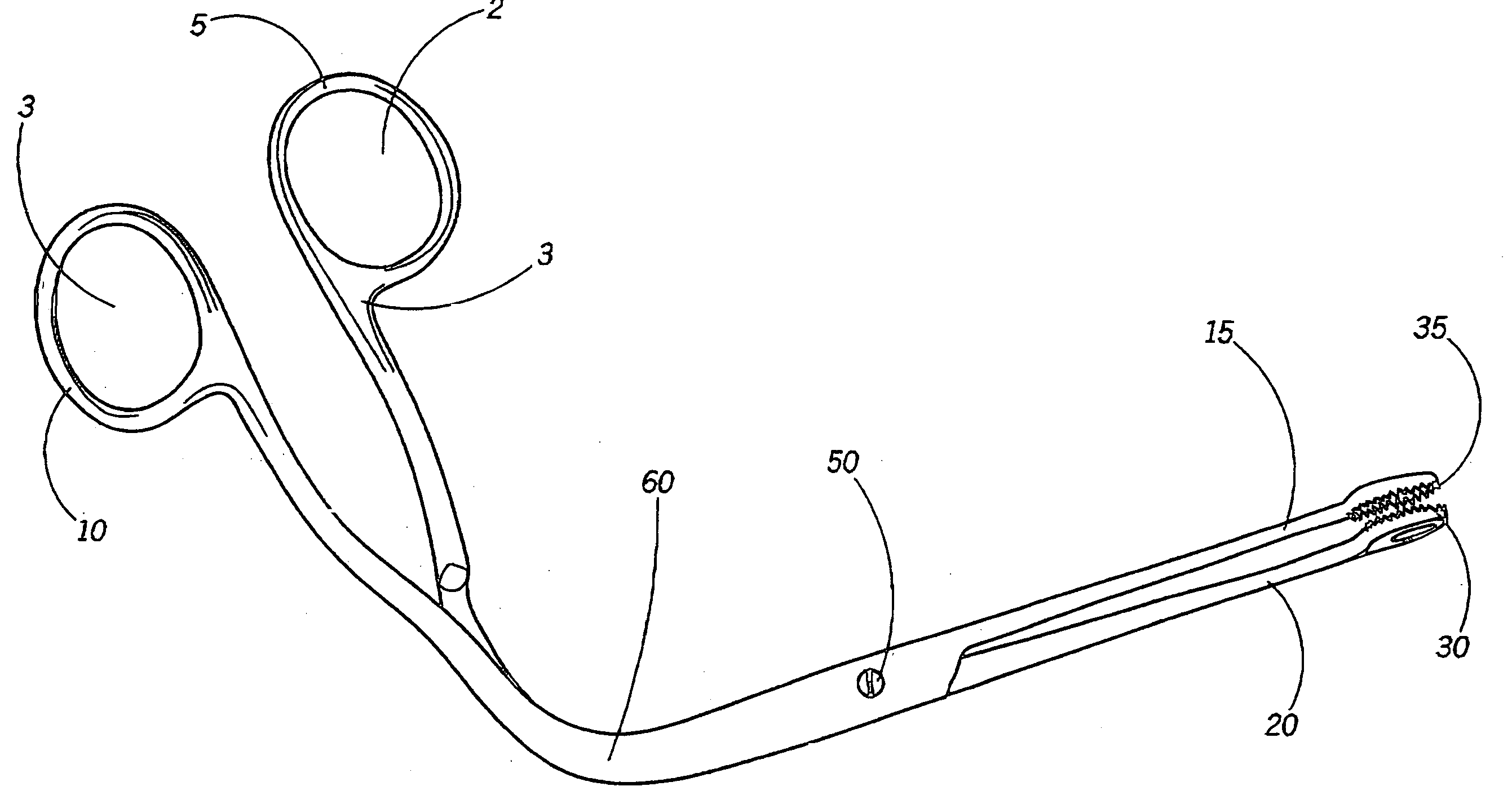
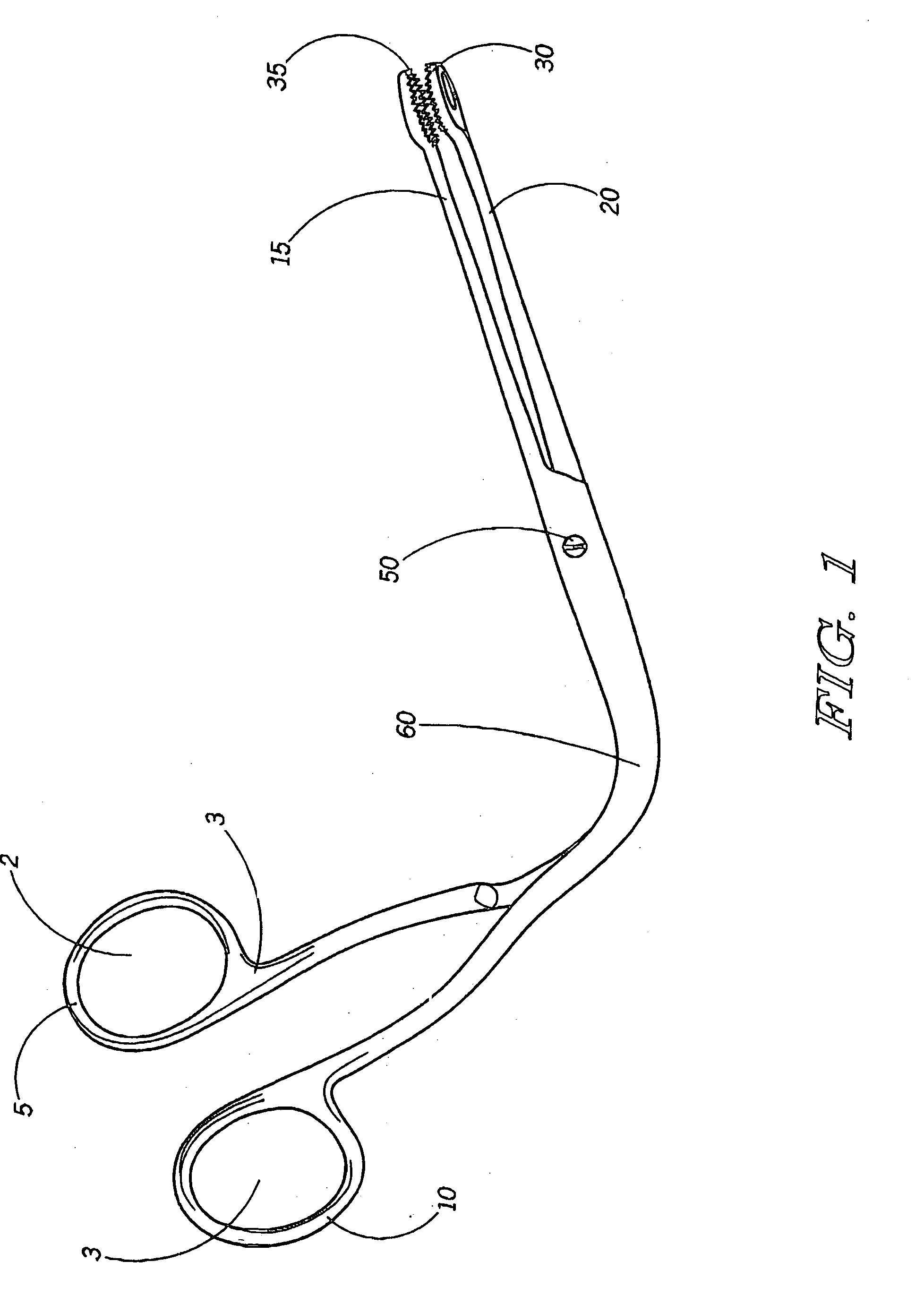
[0022] A catheter guiding device 1 that currently exists in the art is depicted in FIG. 1. A pair of handles 5, 10 each defines an aperture 2, 3 for a user to insert a finger and thumb. The handles 5, 10 are integrally connected to a pair of arms 15, 20. The handle 5 and arm 15 is pivotally connected to the handle 10 and arm 20 through a pivot 50. Each arm 15, 20 has an end 30, 35, respectively, that is D-shaped with parallel, sharp serrations on the interior surfaces. When using this device to insert a catheter into a patient, a medical professional will insert his or her fingers into the apertures 2, 3 and open the handles 5, 10, which correspondingly open the arms 15, 20. The health care professional will then close the handles 5, 10, accordingly closing the arms 15, 20, so that the ends 30, 35 grip the catheter. The device 1 is then used to push the catheter through the patient's vocal cords to allow ventilation or to insert the catheter into any other part of the patient's body...
PUM
 Abstract
Description
Claims
Application Information