Connectivity fault notification

a fault notification and network technology, applied in the field of network communication, can solve problems such as alarms that overwhelm an nms/os, alarms generated, and protocols to environments that were not originally intended

Inactive Publication Date: 2006-02-09
RPX CLEARINGHOUSE
View PDF25 Cites 105 Cited by
  • Summary
  • Abstract
  • Description
  • Claims
  • Application Information

AI Technical Summary

Benefits of technology

[0008] A network device in accordance with the invention may include circuitry operable to detect a connectivity fault or failure, which could include loss of continuity and misconnections, logically adjacent to the device; logic operable to generate an alarm indication signal in response to detection of the connectivity failure; and at least one port operable to forward the alarm indication signal to at least one client level entity. The device is operable to periodically retransmit the alarm indication signal, e.g., once per second. The device may also include a memory operable to maintain a record including bindings of Destinati

Problems solved by technology

However, the extension of such protocols to environments in which they were not originally intended presents some problems.
One problem is that a single failure can trigger a cascade of alarms that overwhelm an NMS/OSS.
However, the o

Method used


Image

  • Connectivity fault notification
  • Connectivity fault notification
  • Connectivity fault notification

Examples


Embodiment Construction

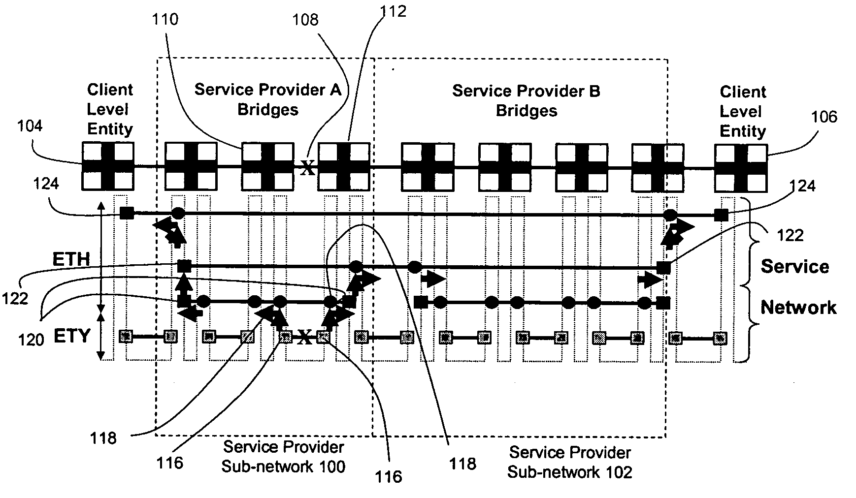
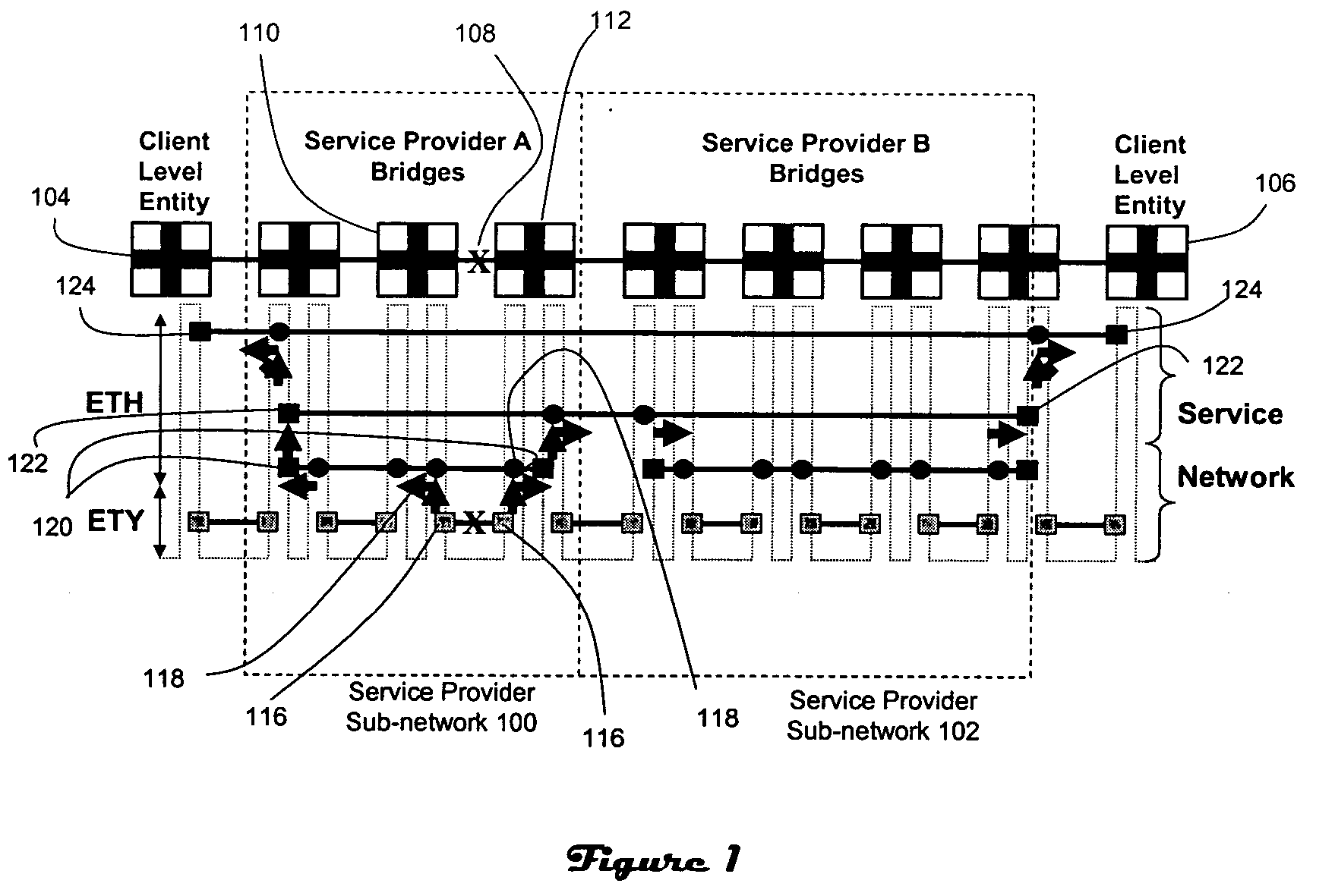
[0014]FIGS. 1 and 2 illustrate a technique for delivering an indication of a network fault that affects an Ethernet-based service such as VLANs. The end-to-end network includes a first service provider sub-network (100), a second service provider sub-network (102), and client level entities (104, 106) associated with customer networks. Initially, a fault (108) is detected at the Ethernet physical layer (“ETY”) by nodes such as bridges (110, 112) that are logically adjacent to the fault. The fault may be a link failure, node failure or misconnection. Further, the fault could be detected at any layer of the OSI model. In response to detection of the fault, the nodes that are logically adjacent to the failed link (108) prompt generation of an Alarm Indication Signal (“AIS”) (200). In particular, Maintenance End Points (“MEPs”) (116) on either side of the fault each generate an AIS (114) which is forwarded by Maintenance Intermediate Points (“MIPs”) (118) at the next higher ME level tow...


PUM


Abstract

Connectivity fault notification is provided by generating an alarm indication signal at a device that is logically adjacent to the fault, and forwarding the alarm indication signal upward through various levels to at least one client level entity. The alarm indication signal may be suppressed at any level for a service instance if service is restored at that level, or if a protection path prevents disruption of the service instance at that level, or auto-suppressed at an originating node based on number of times transmitted or elapsed time. The alarm indication signal may include a point of failure indicator such as the MAC address of the device that generates the alarm indication signal, or a failed resource identity such as an IEEE 802.1AB LLDP MAC Service Access Point (“MSAP”). Further, the alarm indication signal may be employed to trigger use of the protection path.

Description

CROSS-REFERENCE TO RELATED APPLICATIONS [0001] A claim of priority is made to U.S. Provisional Patent Application Ser. No. 60 / 574,253, entitled METHOD AND SYSTEM FOR CONNECTIVITY FAULT NOTIFICATION, filed May 25, 2004, and U.S. Provisional Patent Application Ser. No. 60 / 575,772, entitled METHOD AND SYSTEM FOR CONNECTIVITY FAULT NOTIFICATION, filed May 28, 2004, both of which are incorporated by reference.FIELD OF THE INVENTION [0002] This invention is generally related to the field of network communications, and more particularly to fault notifications associated with connectivity failures. BACKGROUND OF THE INVENTION [0003] Ethernet and other communications protocols that were once used only in Local Area Network (“LAN”) environments are now being used in Metropolitan Area Networks (“MANs”) and Wide Area Networks (“WANs”). One reason for this development is that Enterprises and other customers of communications Service Providers find it convenient to operate, end-to-end, in an envi...

Claims


Application Information

Patent Timeline
IPC IPC(8): G06F15/173G06F11/00H04L12/24H04L12/46
CPCH04L12/4641H04L41/0631H04L41/0663H04L41/0686Y02B60/43G06F11/0772H04L41/0677Y02D30/00H04L41/40
Inventor MOHAN, DINESHHOLNESS, MARC
Owner RPX CLEARINGHOUSE
Why Eureka
Try Eureka