Brush assembly of cleaner

Inactive Publication Date: 2006-02-16
LG ELECTRONICS INC
View PDF12 Cites 35 Cited by
  • Summary
  • Abstract
  • Description
  • Claims
  • Application Information

AI Technical Summary

Benefits of technology

[0011] Therefore, an object of the present invention is to provide a brush assembly of a cleaner capable of preventing

Problems solved by technology

However, because the brush driving force transfer device in accordance with the conventional art mechanically transfers a rotary force of the d

Method used


Image

  • Brush assembly of cleaner
  • Brush assembly of cleaner
  • Brush assembly of cleaner

Examples


Embodiment Construction

[0028] Reference will now be made in detail to the preferred embodiments of the present invention, examples of which are illustrated in the accompanying drawings.

[0029] A plurality of embodiments of a brush assembly of a cleaner in accordance with the present invention may exist, and the most embodiment will be described.

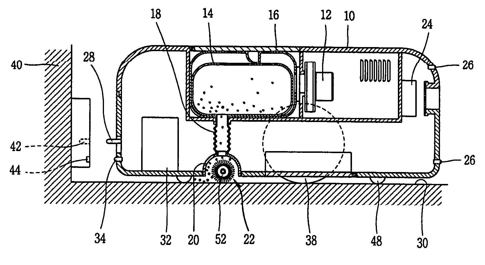
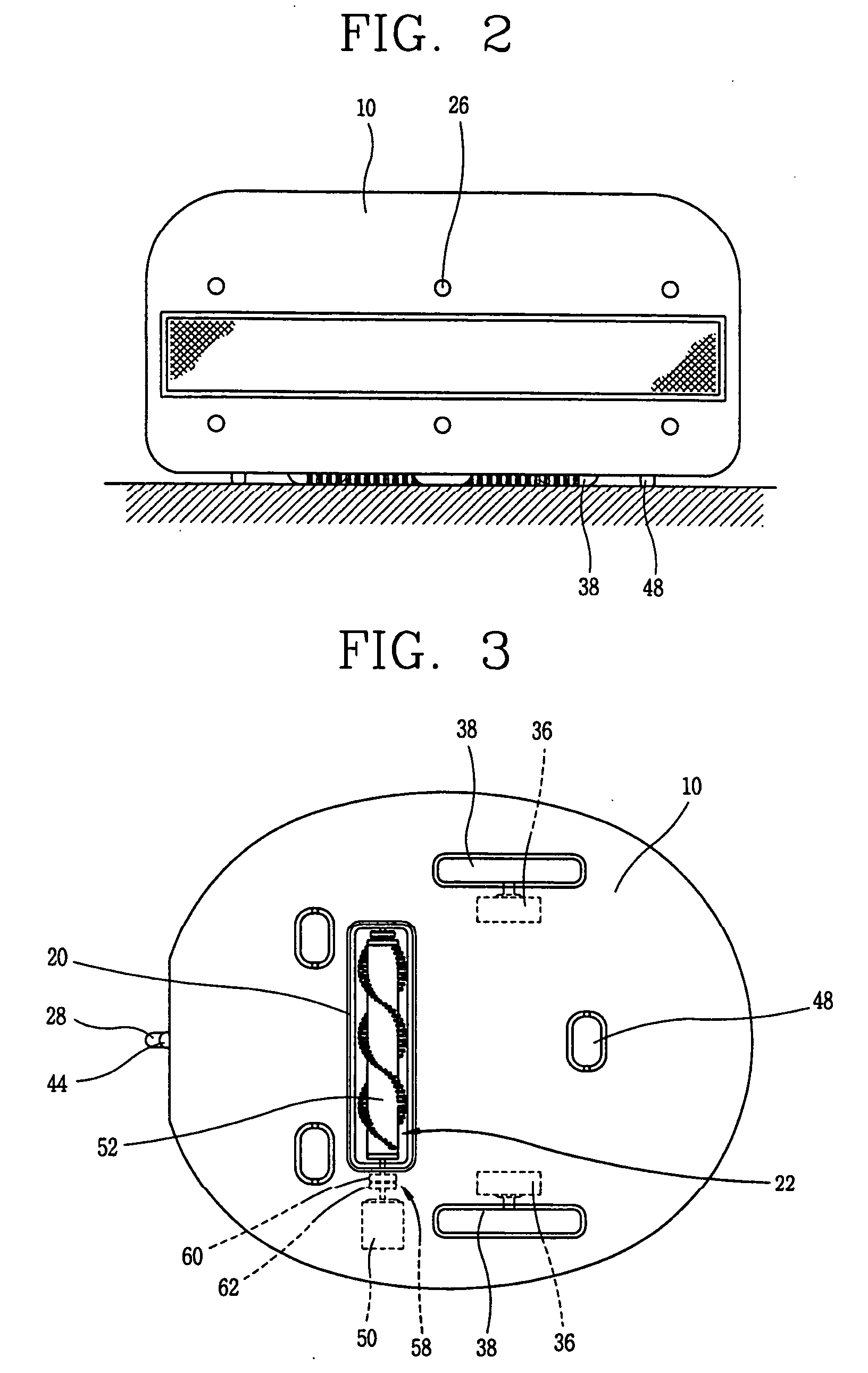
[0030]FIG. 2 is a side view of a robot cleaner in accordance with one embodiment of the present invention, FIG. 3 is a rear view of the robot cleaner in accordance with one embodiment of the present invention, and FIG. 4 is a sectional view of the robot cleaner in accordance with one embodiment of the present invention.

[0031] The robot cleaner in accordance with the present invention includes: a cleaner main body 10; a suction fan 12 mounted in the cleaner main body 10, for generating a suction force of the cleaner; a filter container 16 mounted in front of the suction fan 12 and having therein a filter 14 for collecting dirt or filth sucked by the suction fan 12...


PUM


Abstract

A brush assembly of a cleaner includes a driving motor mounted at a cleaner main body, for generating a rotary force; a brush rotatably disposed at a suction opening formed at the cleaner main body; and a driving force transfer device installed between the driving motor and the brush, rotating the brush by transferring a rotary force of the driving motor to the brush, and protecting the driving motor by preventing transfer of a load generated at the brush to the driving motor. Accordingly, the driving motor can be continuously rotated even if the brush cannot be rotated by being caught by a stuff or the like, thereby preventing motor damage.

Description

BACKGROUND OF THE INVENTION [0001] 1. Field of the Invention [0002] The present invention relates to a brush assembly of a cleaner, and particularly, to a brush assembly of a cleaner capable of preventing motor damage by keeping the motor rotating when a brush cannot be rotated by being caught by a stuff or the like. [0003] 2. Description of the Background Art [0004] In general, a robot cleaner performs a cleaning operation while moving for itself without manipulation of a user, moves to a charging station if power of a battery is consumed during cleaning, and moves back to a cleaning zone to perform a cleaning operation when the battery charge is completed. [0005] A brush assembly for sweeping up dirt or foreign substances from a floor is installed at a suction opening through which dirt is sucked, of the robot cleaner. [0006]FIG. 1 is a side view showing a brush assembly of a robot cleaner in accordance with the conventional art. [0007] The brush assembly in accordance with the co...

Claims


Application Information

Patent Timeline
IPC IPC(8): A47L5/00
CPCA47L9/0009A47L2201/00A47L9/0411A47L9/28A47L11/00A47L11/02
Inventor KIM, YOUNG-GIE
Owner LG ELECTRONICS INC
Why Eureka
Try Eureka