Waterwheel powered air delivery device

Inactive Publication Date: 2006-02-16
KAUFMAN MICHAEL J
View PDF17 Cites 21 Cited by
  • Summary
  • Abstract
  • Description
  • Claims
  • Application Information

AI Technical Summary

Benefits of technology

[0015] For use in aerating wastewater, the air delivery device will include a system of pipe's or conduits which deliver the air into the wastewater by a nozzle including one

Problems solved by technology

It is also sometimes necessary to treat wastewater in locations or localities where there is no readily available source of

Method used


Image

  • Waterwheel powered air delivery device
  • Waterwheel powered air delivery device
  • Waterwheel powered air delivery device

Examples


Embodiment Construction

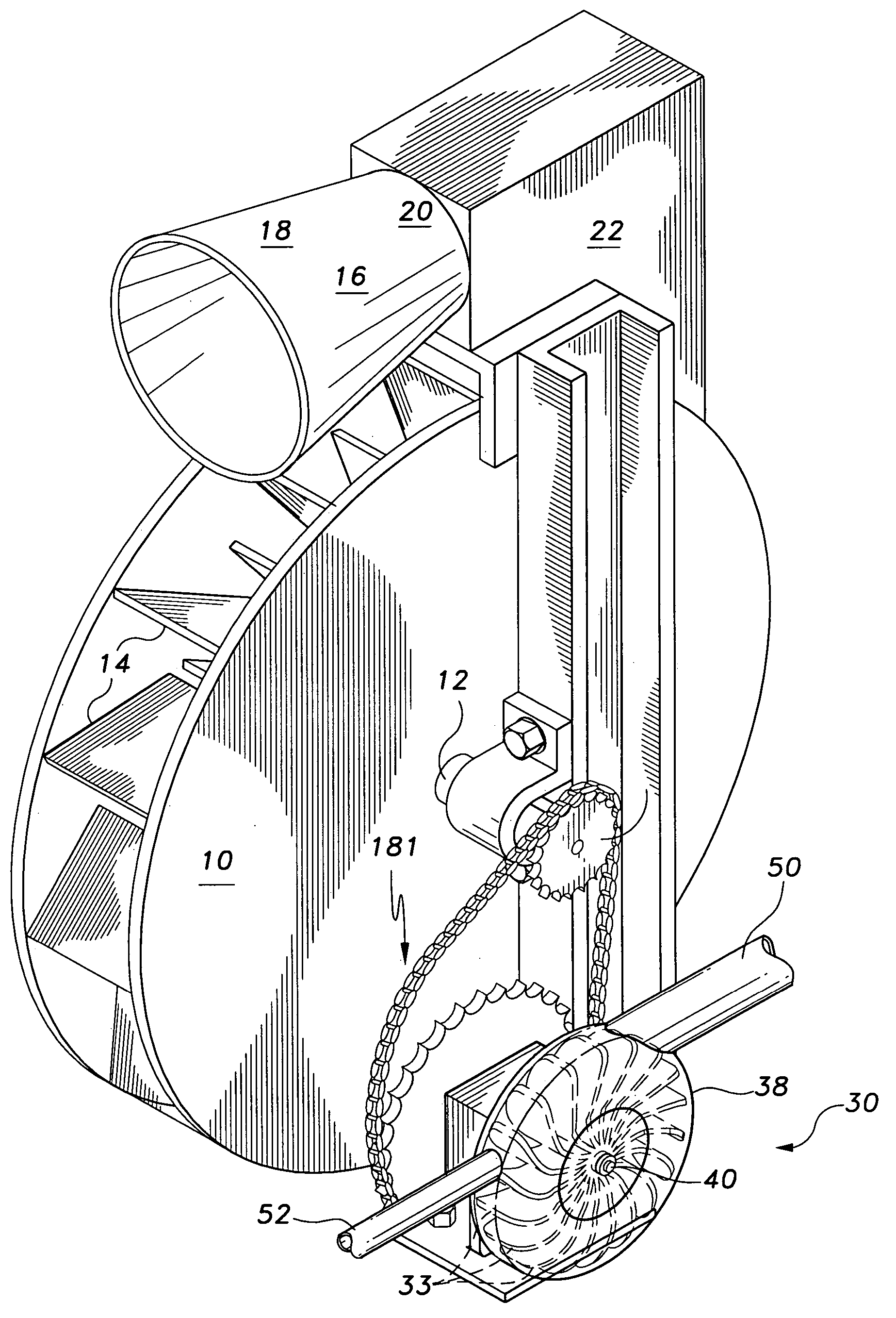
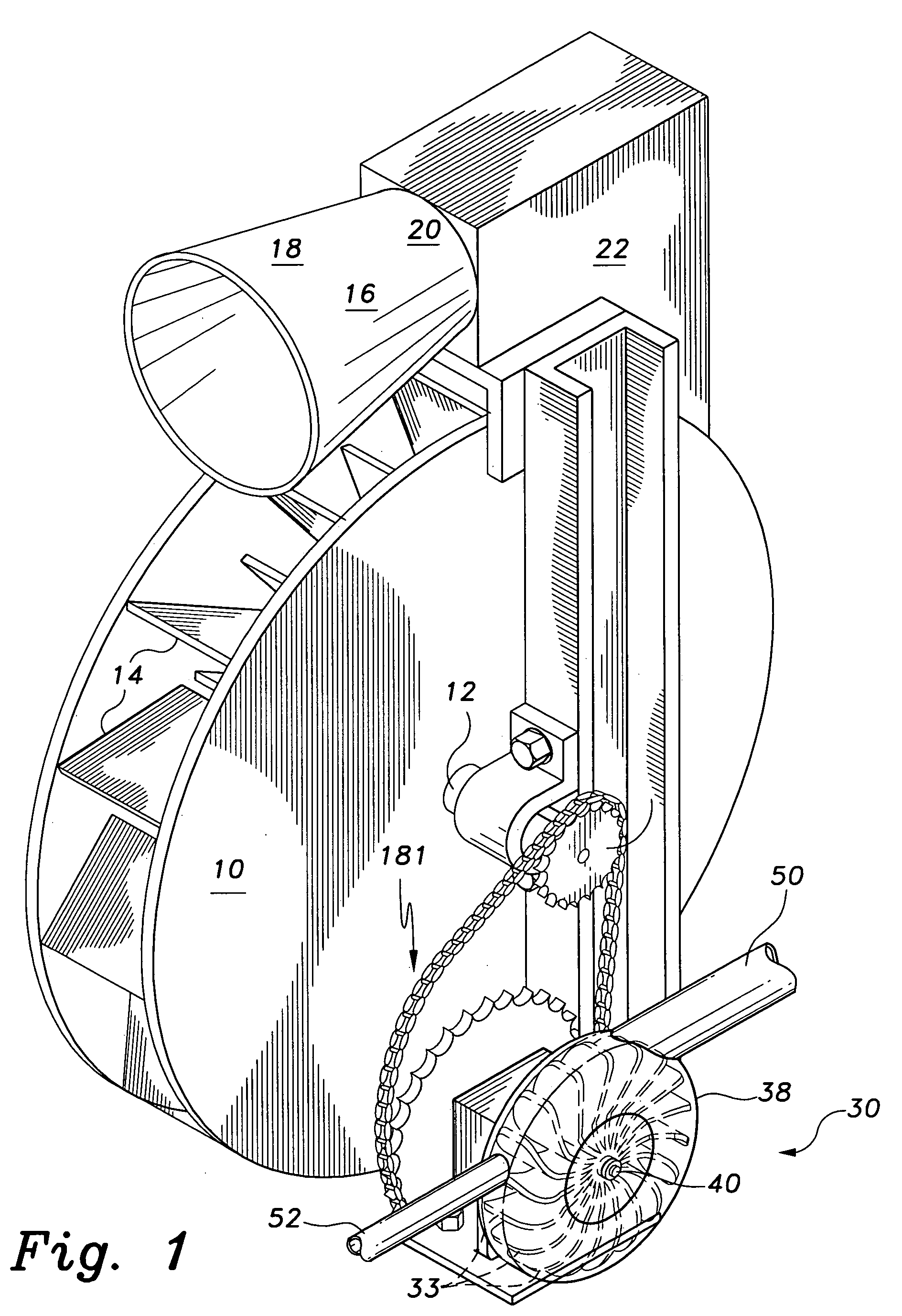
[0021] The present invention is a waterwheel powered air delivery device. As shown in FIG. 1, the system includes at least a waterwheel 10 and an air pump 30. The waterwheel 10 is of the type that is powered by a moving stream of water from a river, brook, creek, pond, stream, or other natural waterway, or from a millrace, flume, or other artificial channel of flowing water. The waterwheel 10 may be an overshot wheel, as shown in the drawings, a breast wheel, or where the head is not sufficient, an undershot or sideshot wheel. The air pump 30 may be a rotary vane pump, as shown in FIG. 1, a diaphragm pump, piston pump, rotary screw pump, or any other type of air pump. Acceptable types of waterwheels and air pumps for use with the present invention are shown and described in detail in my prior patent, U.S. Pat. No. 6,029,688, issued Feb. 29, 2000, which is hereby incorporated by reference in its entirety.

[0022]FIG. 2 shows a representative waterwheel as described in the '688 patent....


PUM


Abstract

The waterwheel powered air delivery device is a system for powering an air compressor, aerator, or other device that moves air from power produced by a waterwheel without the necessity of providing electricity from an outside power source or the intermediate production of electricity from the waterwheel. The waterwheel may be an overshot, undershot or sideshot waterwheel. The device being powered may be an air compressor, aerator, or other air delivery device having an air pump that may be of the diaphragm, piston, rotary vane, rotary screw or other type. Preferably the air produced by the waterwheel and air delivery device is used for aeration of wastewater, although the delivery device may be used for other purposes, e.g., ventilation, power, etc.

Description

BACKGROUND OF THE INVENTION [0001] 1. Field of the Invention [0002] The present invention relates to water powered air compressors, aerators, and other air conveying devices, and more particularly to air delivery devices powered by a waterwheel run by flowing water. [0003] 2. Description of the Related Art [0004] Wastewater treatment facilities use a variety of methods for removing environmental pollutants from wastewater. Frequently it is desirable to aerate the wastewater during treatment to aid in separating contaminants from the water (particularly noxious gases entrained in the wastewater), and to replace any oxygen depleted from the water upon discharge for the benefit of fish and wildlife. A further goal would be to aerate the water in an environmentally friendly manner by using an energy source that does not rely upon electricity derived from generators powered by fossil fuels. It is also sometimes necessary to treat wastewater in locations or localities where there is no re...

Claims


Application Information

Patent Timeline
IPC IPC(8): F03B13/00H02P9/04
CPCF01C11/006F03B7/00F04C18/16Y02E10/223F04C23/02F04D25/04F04C23/005Y02E10/20Y02P70/50
Inventor KAUFMAN, MICHAEL J.
Owner KAUFMAN MICHAEL J
Why Eureka
Try Eureka