Method of operating a controlled roller blind supplied by way of a wire control interface

a technology of wire control interface and control box, which is applied in the direction of position/direction control, ac motor stoppers, building components, etc., can solve the problems of difficult implementation of the procedure allowing the device to switch to a configuration mode, the device cannot operate with control boxes of fixed type, and the device cannot operate with certain types of control boxes alone. , to achieve the effect of simple structure and easy reconfiguration and operation of the actuator

Inactive Publication Date: 2006-02-16
SOMFY SAS
View PDF3 Cites 16 Cited by
  • Summary
  • Abstract
  • Description
  • Claims
  • Application Information

AI Technical Summary

Benefits of technology

[0020] The aim of the invention is to provide a method of operation of an actuator making it possible to alleviate the drawbacks cited previously and to improve the methods of operation of the actuators known in the prior art. In particular, the invention proposes a method of operation of an actuator in which the configuration and the reconfiguration of the actuator are easy and which makes it possible to retain functions of displacement of the actuator by way of the control interface and to enable settings to be adjusted without any risk of activation of a control key causing a movement of the actuator. Furthermore, it is desirable that the method of control make possible the use of a control interface of very simple structure (for example consisting of a box furnished with two keys) and that this method endow this interface with a significant number of functions. It is finally desirable that this method be implementable by a device comprising an interface of any type whatsoever and, in particular, of the type whose keys consist of pushbuttons, of double switches with maintained position or of toggle switches.

Problems solved by technology

Such a device can only operate with certain types of control boxes alone.
In particular, this device cannot operate with control boxes of inverter type with fixed or momentary position with mechanical exclusion.
This kind of procedure allowing the device to switch to a configuration mode is fairly difficult to implement when the control box is a fixed-position inverter.
Such a device is rather impractical since it always necessitates sequential control of the movements of the garage door.

Method used


Image

  • Method of operating a controlled roller blind supplied by way of a wire control interface
  • Method of operating a controlled roller blind supplied by way of a wire control interface
  • Method of operating a controlled roller blind supplied by way of a wire control interface

Examples


Embodiment Construction

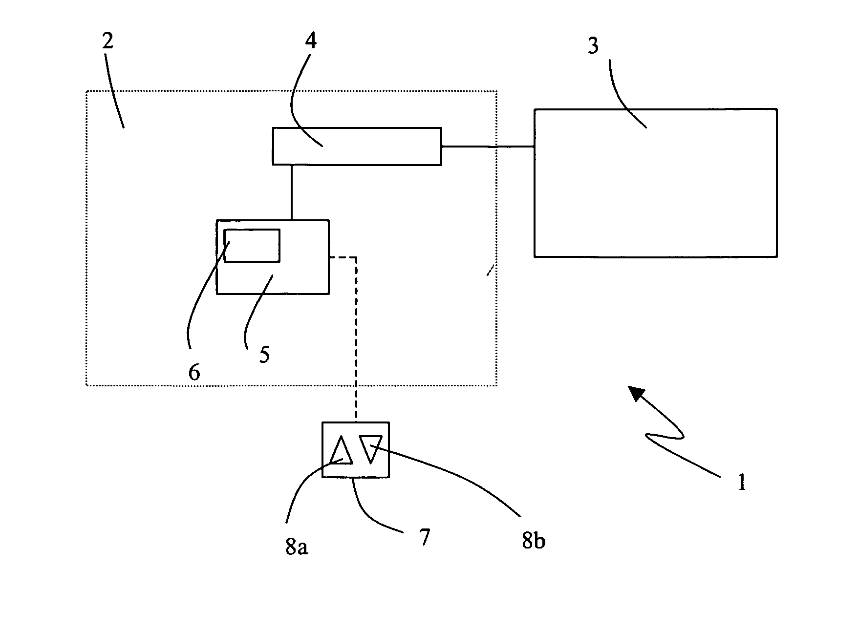
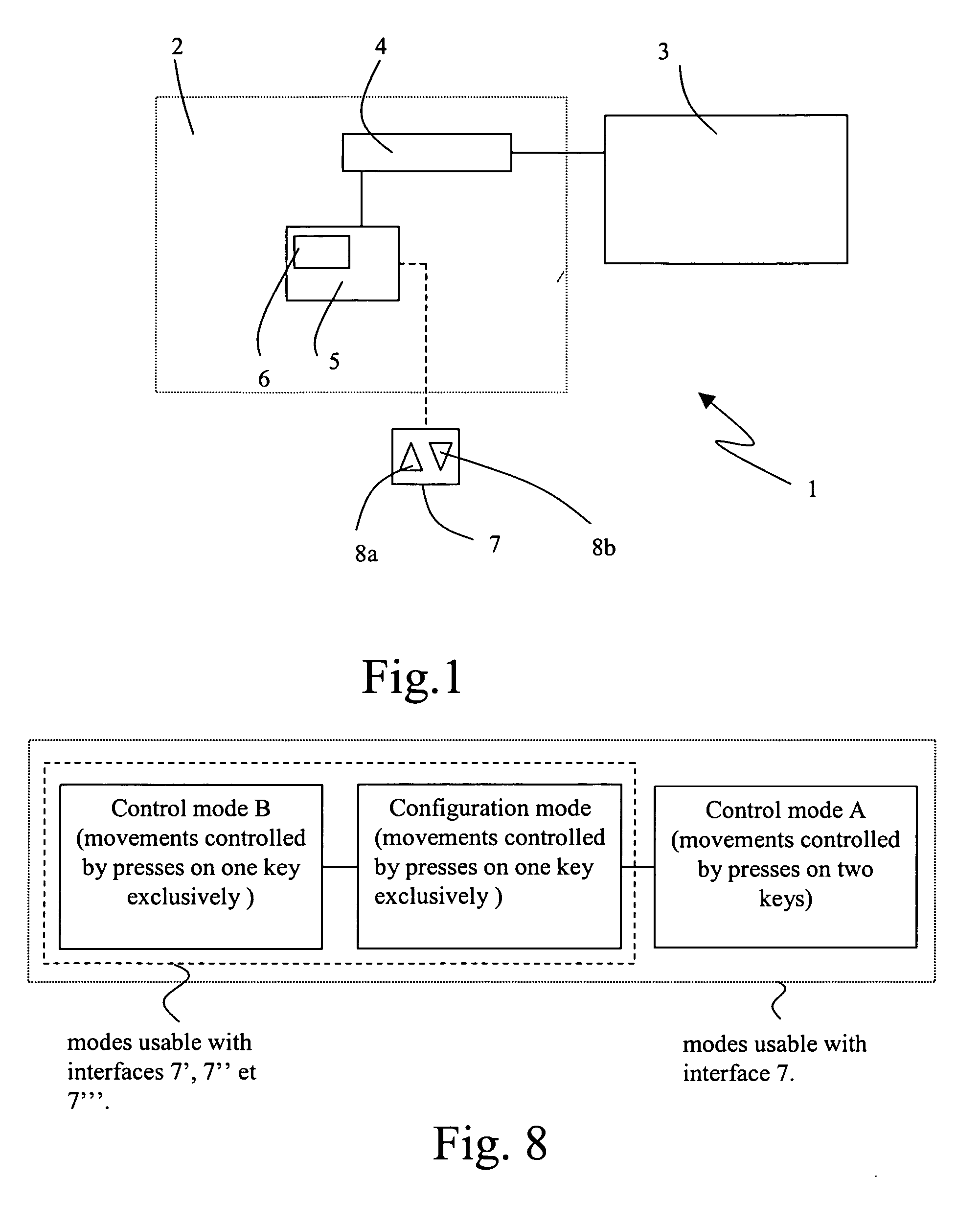
[0033] An actuator 1 is represented diagrammatically in FIG. 1. It comprises mainly a control interface 7 and an actuation unit 2 comprising an electronic control unit 5 and a motor 4. The actuation unit is tied mechanically, possibly by way of a reducing gear, to a movable element 3 for closure, privacy or solar protection or a projection screen so as to drive the displacement of the latter. The movable element 3 may in particular consist of a roller blind, a shutter or a door. The electronic control unit 5 is tied to the motor 4, it ensures the command of the movements of the latter by way of its supply. The electronic control unit comprises a memory 6, and moreover has the function of determining the position in which the movable element 3 is to be found at each instant. The actuation unit can comprise for this purpose a counting device associated with a sensor of Hall-effect type or of optoelectronic type for example.

[0034] To allow a user to control the movements of the movabl...


PUM


Abstract

The method of operating an actuator intended to drive a movable element for closure, for privacy or for solar protection or a projection screen, comprising a motor, an electronic unit for controlling the supply to the motor and a control interface furnished with at least one first key and a second key, the pressing of which keys usually causes a movement of the motor in a first direction, respectively, a movement of the motor in a second direction, is one wherein, in at least one first mode of operation, the movements of the motor in the two directions are controlled by presses of the first key exclusively.

Description

FIELD OF THE INVENTION [0001] The invention relates to a method of operating an actuator intended to drive a movable element for closure, for privacy or for solar protection or a projection screen, comprising a motor, an electronic unit for controlling the supply to the motor and a control interface furnished with at least one first key and a second key, the pressing of which keys usually causes a movement of the motor in a first direction, respectively, a movement of the motor in a second direction. The invention also relates to an actuation unit and to an actuator for the implementation of the method. [0002] Such actuators are used to maneuver, by virtue of the mechanical energy provided by the motor, movable elements for closure, for privacy or for solar protection. A user can control the displacements of this element by presses of the control keys of a control interface. [0003] In the cases of very simple control interfaces comprising only two keys associated with the two direct...

Claims


Application Information

Patent Timeline
Patent Type & Authority Applications(United States)
IPC IPC(8): H02P7/00E06B9/68
CPCE06B9/68
Inventor D'AYOT, GEOFFROY DUMONT
Owner SOMFY SAS
Why Eureka
Try Eureka