
System for Configuring Hardware in a Downhole Tool

a technology for configuring hardware and tools, applied in instruments, borehole/well accessories, surveys, etc., can solve problems such as constant updates, affecting the operation of on-site crew, and requiring portions of executable code to be rewritten

Active Publication Date: 2006-02-16
INTELLISERV
View PDF72 Cites 11 Cited by
  • Summary
  • Abstract
  • Description
  • Claims
  • Application Information

AI Technical Summary

Benefits of technology

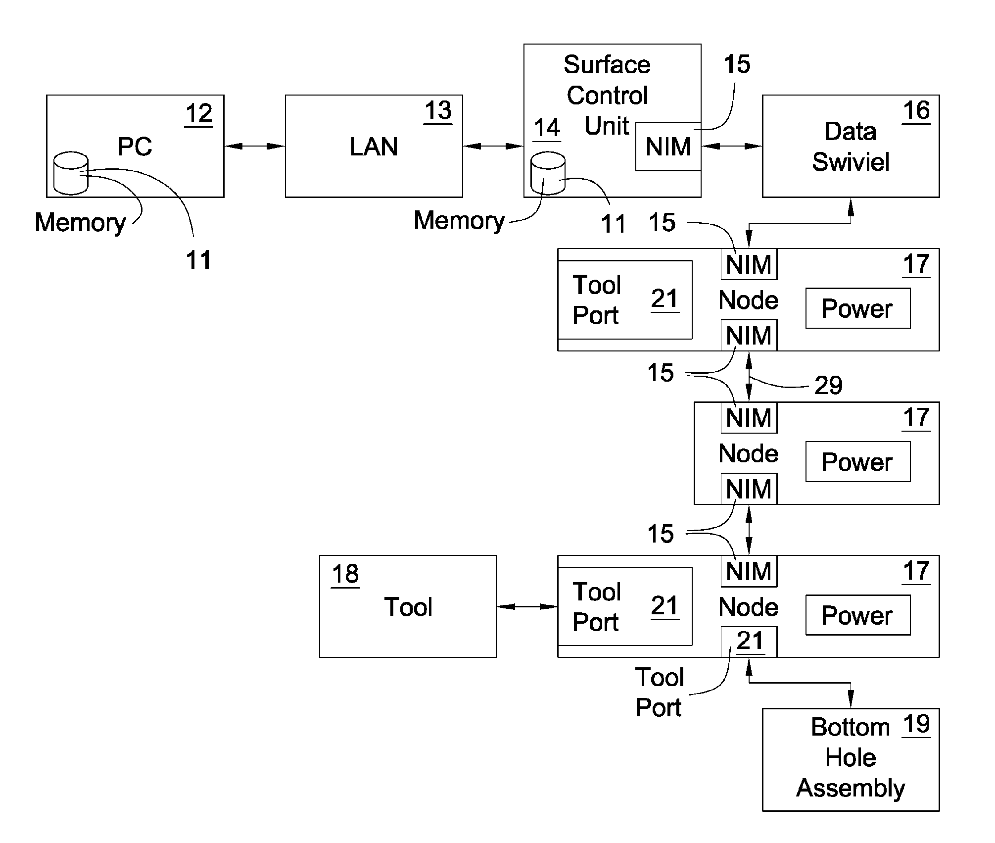
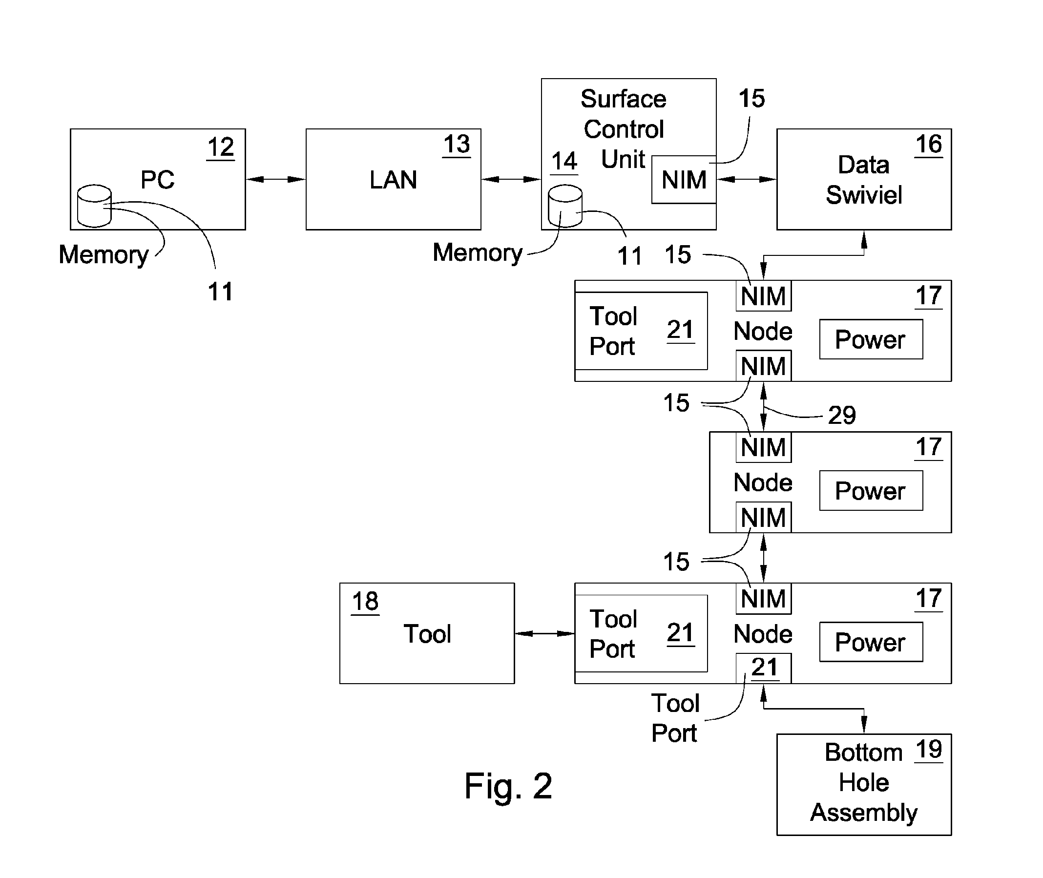
[0007] In accordance with one aspect of the invention, the system includes a surface control unit at the surface of a drilling or production well site. The surface control unit comprises a hardware configuration, preferably stored as binary data, transmits it over a downhole network integrated into a tool string to configurable hardware in a downhole tool component. The downhole network is preferably the one described in the aforementioned '880 patent. However other compatible systems for transmitting data from the surface to a downhole component are disclosed in U.S. Pat. Nos. 6,688,396 and 6,641,434 to Floerke and Boyle respectively, both of which are herein incorporated by reference. The downhole string component is preferably a node in the downhole network or a tool in the tool string such as a jar, a motor, a shock absorber, a hammer, or a drill bit, all of which may be associated with a node in the downhole network.
[0008] The hardware configuration transmitted over the downhole network is implemented in the configurable hardware, which is preferably a field programmable gate array (FPGA). The hardware configuration may adapt the configurable hardware to be able to perform one or more desired downhole tasks. The downhole tool component itself may comprise modems, application-specifi...

Problems solved by technology

New software may require constant updates to fix errors that result from unforeseen conditions for which the software was not designed.
Updating the executable code of downhole tools complicate the operations of the on-site crew.
Errors in the executable code may require portions of the executable code to be rewritten.
Often removing the entire downhole tool string is required to access the executable code, which is costly and time consuming.
Further complicating the matter is the cost associated with the processors for downhole tools.
The combined cost of all of the processors in the downhole tools may add to several million dollars, which increases if errors in the executable code require replacements.
This system reduces the number of times that a downhole tool's software needs to be replaced, but there is still a significant amount of non-volatile memory downhole.

Method used


Image

  • System for Configuring Hardware in a Downhole Tool
  • System for Configuring Hardware in a Downhole Tool
  • System for Configuring Hardware in a Downhole Tool

Examples


Embodiment Construction

[0021] This specification is meant to illustrate the present invention and not limit its scope. Other embodiments of the present invention are possible within the scope and spirit of the claims.

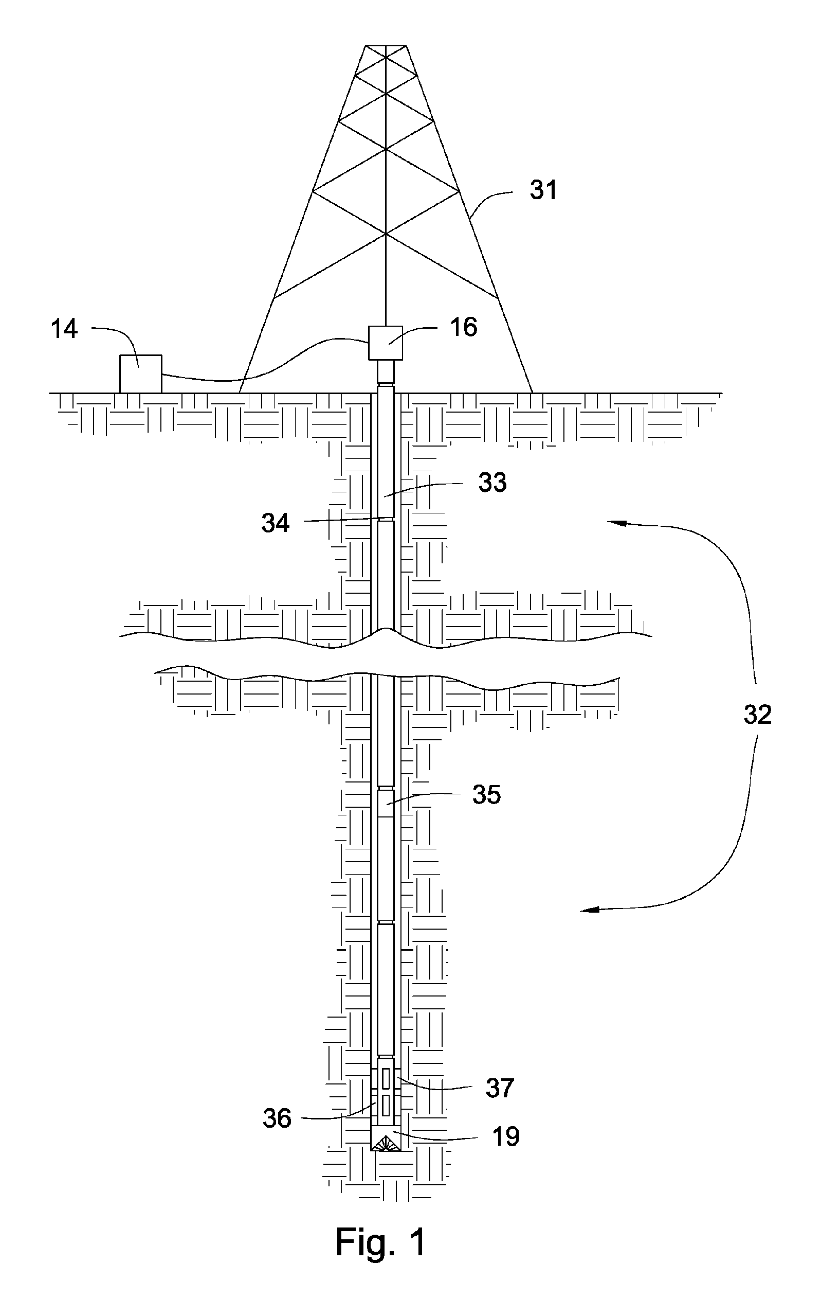
[0022]FIG. 1 shows an embodiment of a downhole tool string 32 in a bore hole. The downhole tool string 32 may be a drill string or it may be part of a production well. A derrick 31 suspends the downhole tool string 32. A data swivel 16 connects the surface control unit 14 to the downhole tool string 32. Components 33 of the downhole tool string 32 may be pipes wherein each pipe comprises a box end and a pin end. The pin end and box end connect together and form a joint 34 in the downhole tool string 32. In the preferred embodiment there are inductive couplers in the pin end and box end of the components 33 of the downhole tool string 32. Alternatively direct electrical couplers may be used.

[0023] Examples of tools on a bottom hole assembly 19 comprise sensors, drill bits, motors, hammers, a...


PUM


Abstract

A system for loading a hardware configuration into downhole configurable hardware includes a surface control unit in communication with a downhole tool string component over a downhole network. The surface control unit initially has the hardware configuration and transmits it through the downhole network to the configurable hardware. The hardware configuration is implemented in the configurable hardware. The configurable hardware is preferably an FPGA.

Description

CROSS REFERENCE TO RELATED APPLICATIONS [0001] The present application is a continuation-in-part of U.S. Ser. application No. 10 / 710,638 filed Jul. 27, 2004 to Hall, et. al. which is herein incorporated by reference.BACKGROUND OF THE INVENTION [0002] This invention relates to a system for loading executable code to volatile memory in a downhole tool, specifically to downhole tools that are part of a downhole tool string. Software for downhole tools on a downhole tool string need to be programmed for numerous conditions. New software may require constant updates to fix errors that result from unforeseen conditions for which the software was not designed. Under some circumstances it is also beneficial to provide specialized software to a downhole tool so that it may perform unique and / or specialized tasks according to the software it has loaded. U.S. Pat. No. 6,670,880 (hereafter referred to as the '880 patent), which is herein incorporated by reference, discloses a system for transmi...

Claims


Application Information

Patent Timeline
IPC IPC(8): G01V3/00
CPCG06F8/665E21B47/12G06F8/654
Inventor HALLJOHNSON, MONTE L.
Owner INTELLISERV
Learn More